Nissan Murano. Manual — part 969
LAN
ECM BRANCH LINE CIRCUIT
LAN-187
< DTC/CIRCUIT DIAGNOSIS >
[CAN SYSTEM (TYPE 8)]
C
D
E
F
G
H
I
J
K
L
B
A
O
P
N
ECM BRANCH LINE CIRCUIT
Diagnosis Procedure
INFOID:0000000010093039
1.
CHECK CONNECTOR
1.
Turn the ignition switch OFF.
2.
Disconnect the battery cable from the negative terminal.
3.
Check the following terminals and connectors for damage, bend and loose connection (unit side and con-
nector side).
-
Models with automatic back door system
•
ECM
•
Harness connector E104
•
Harness connector B4
-
Models without automatic back door system
•
ECM
•
Harness connector E105
•
Harness connector M11
Is the inspection result normal?
YES
>> GO TO 2.
NO
>> Repair the terminal and connector.
2.
CHECK HARNESS FOR OPEN CIRCUIT
1.
Disconnect the connector of ECM.
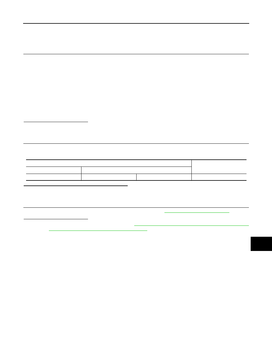
2.
Check the resistance between the ECM harness connector terminals.
Is the measurement value within the specification?
YES
>> GO TO 3.
NO
>> Repair the ECM branch line.
3.
CHECK POWER SUPPLY AND GROUND CIRCUIT
Check the power supply and the ground circuit of the ECM. Refer to
Is the inspection result normal?
YES (Present error)>>Replace the ECM. Refer to
EC-16, "ADDITIONAL SERVICE WHEN REPLACING
CONTROL UNIT : Special Repair Requirement"
YES (Past error)>>Error was detected in the ECM branch line.
NO
>> Repair the power supply and the ground circuit.
ECM harness connector
Resistance (
Ω
)
Connector No.
Terminal No.
E16
98
97
Approx. 108 – 132
LAN-188
< DTC/CIRCUIT DIAGNOSIS >
[CAN SYSTEM (TYPE 8)]
4WD BRANCH LINE CIRCUIT
4WD BRANCH LINE CIRCUIT
Diagnosis Procedure
INFOID:0000000010093041
1.
CHECK CONNECTOR
1.
Turn the ignition switch OFF.
2.
Disconnect the battery cable from the negative terminal.
3.
Check the terminals and connectors of the AWD control unit for damage, bend and loose connection (unit
side and connector side).
Is the inspection result normal?
YES
>> GO TO 2.
NO
>> Repair the terminal and connector.
2.
CHECK HARNESS FOR OPEN CIRCUIT
1.
Disconnect the connector of AWD control unit.
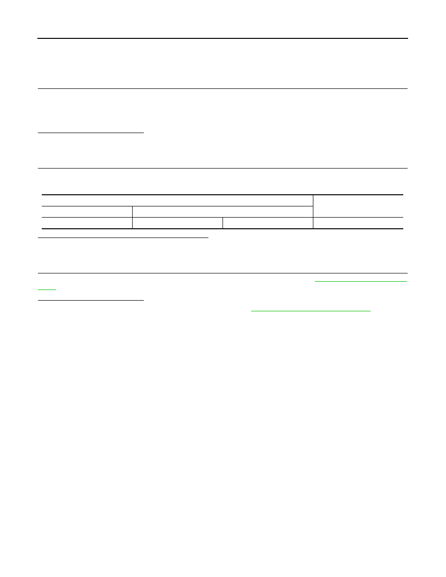
2.
Check the resistance between the AWD control unit harness connector terminals.
Is the measurement value within the specification?
YES
>> GO TO 3.
NO
>> Repair the AWD control unit branch line.
3.
CHECK POWER SUPPLY AND GROUND CIRCUIT
Check the power supply and the ground circuit of the AWD control unit. Refer to
.
Is the inspection result normal?
YES (Present error)>>Replace the AWD control unit. Refer to
DLN-53, "Removal and Installation"
YES (Past error)>>Error was detected in the AWD control unit branch line.
NO
>> Repair the power supply and the ground circuit.
AWD control unit harness connector
Resistance (
Ω
)
Connector No.
Terminal No.
M69
8
16
Approx. 54 – 66
LAN
HVAC BRANCH LINE CIRCUIT
LAN-189
< DTC/CIRCUIT DIAGNOSIS >
[CAN SYSTEM (TYPE 8)]
C
D
E
F
G
H
I
J
K
L
B
A
O
P
N
HVAC BRANCH LINE CIRCUIT
Diagnosis Procedure
INFOID:0000000010093136
1.
CHECK CONNECTOR
1.
Turn the ignition switch OFF.
2.
Disconnect the battery cable from the negative terminal.
3.
Check the terminals and connectors of the A/C auto amp. for damage, bend and loose connection (unit
side and connector side).
Is the inspection result normal?
YES
>> GO TO 2.
NO
>> Repair the terminal and connector.
2.
CHECK HARNESS FOR OPEN CIRCUIT
1.
Disconnect the connector of A/C auto amp.
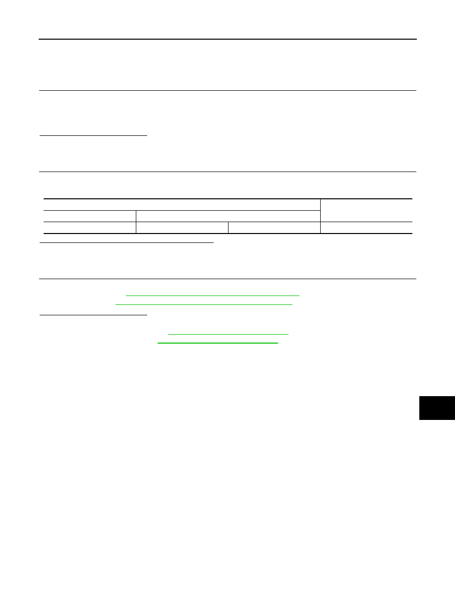
2.
Check the resistance between the A/C auto amp. harness connector terminals.
Is the measurement value within the specification?
YES
>> GO TO 3.
NO
>> Repair the A/C auto amp. branch line.
3.
CHECK POWER SUPPLY AND GROUND CIRCUIT
Check the power supply and the ground circuit of the A/C auto amp. Refer to the following.
• Without 7 inch display:
HAC-77, "A/C AUTO AMP. : Diagnosis Procedure"
• With 7 inch display:
HAC-202, "A/C AUTO AMP. : Diagnosis Procedure"
Is the inspection result normal?
YES (Present error)>>Replace the A/C auto amp. Refer to the following.
• Without 7 inch display:
VTL-25, "Removal and Installation"
• With 7 inch display:
VTL-89, "Removal and Installation"
YES (Past error)>>Error was detected in the A/C auto amp. branch line.
NO
>> Repair the power supply and the ground circuit.
A/C auto amp. harness connector
Resistance (
Ω
)
Connector No.
Terminal No.
M50
1
2
Approx. 54 – 66
LAN-190
< DTC/CIRCUIT DIAGNOSIS >
[CAN SYSTEM (TYPE 8)]
M&A BRANCH LINE CIRCUIT
M&A BRANCH LINE CIRCUIT
Diagnosis Procedure
INFOID:0000000010093137
1.
CHECK CONNECTOR
1.
Turn the ignition switch OFF.
2.
Disconnect the battery cable from the negative terminal.
3.
Check the terminals and connectors of the combination meter for damage, bend and loose connection
(unit side and connector side).
Is the inspection result normal?
YES
>> GO TO 2.
NO
>> Repair the terminal and connector.
2.
CHECK HARNESS FOR OPEN CIRCUIT
1.
Disconnect the connector of combination meter.
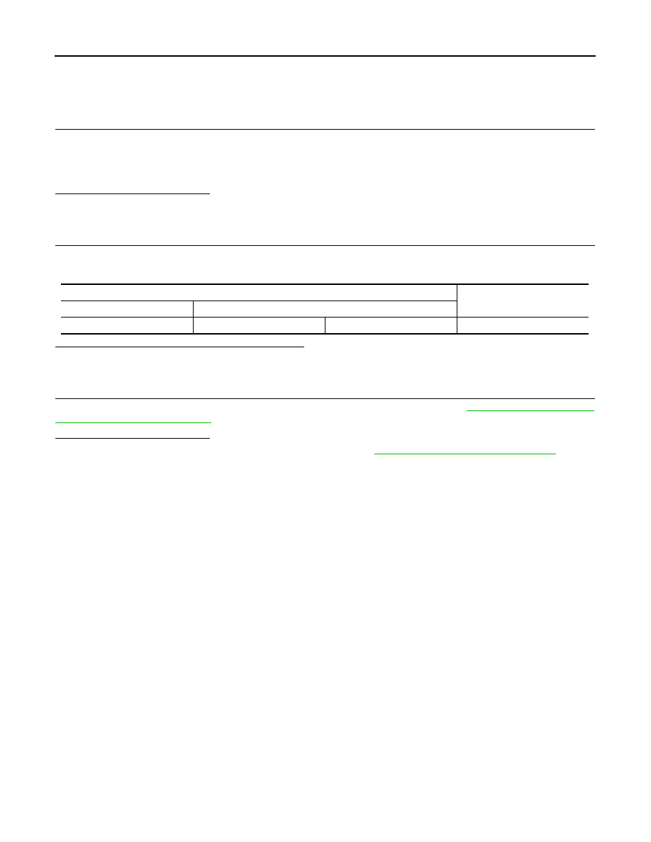
2.
Check the resistance between the combination meter harness connector terminals.
Is the measurement value within the specification?
YES
>> GO TO 3.
NO
>> Repair the combination meter branch line.
3.
CHECK POWER SUPPLY AND GROUND CIRCUIT
Check the power supply and the ground circuit of the combination meter. Refer to
Is the inspection result normal?
YES (Present error)>>Replace the combination meter. Refer to
MWI-105, "Removal and Installation"
YES (Past error)>>Error was detected in the combination meter branch line.
NO
>> Repair the power supply and the ground circuit.
Combination meter harness connector
Resistance (
Ω
)
Connector No.
Terminal No.
M34
21
22
Approx. 54 – 66
Нет комментариевНе стесняйтесь поделиться с нами вашим ценным мнением.
Текст