Nissan Murano. Manual — part 1489
WW-24
< SYSTEM DESCRIPTION >
DIAGNOSIS SYSTEM (IPDM E/R)
CONSULT Function (IPDM E/R)
INFOID:0000000010129277
APPLICATION ITEM
CONSULT performs the following functions via CAN communication with IPDM E/R.
SELF DIAGNOSTIC RESULT
DATA MONITOR
NOTE:
The following table includes information (items) inapplicable to this vehicle. For information (items) applicable
to this vehicle, refer to CONSULT display items.
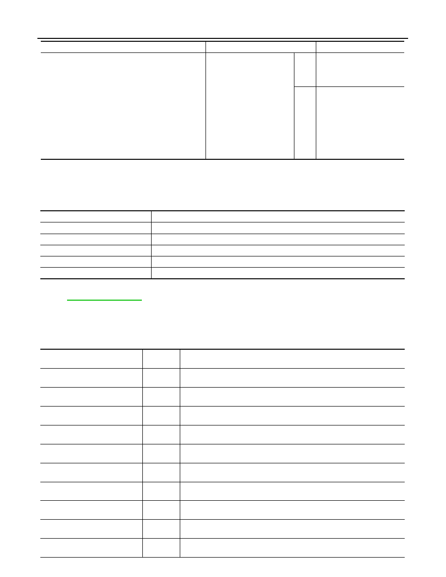
Cooling fan does not operate
Perform auto active test.
Does the cooling fan operate?
YES
• ECM signal input circuit
• CAN communication signal
between ECM and IPDM E/
R
NO
• Harness or connector be-
tween IPDM E/R and cool-
ing fan motor
• Harness or connector be-
tween IPDM E/R and cool-
ing fan relay
• Cooling fan motor
• Cooling fan relay
• IPDM E/R
Symptom
Inspection contents
Possible cause
Diagnosis mode
Description
Ecu Identification
Allows confirmation of IPDM E/R part number.
Self Diagnostic Result
Displays the diagnosis results judged by IPDM E/R.
Data Monitor
Displays the real-time input/output data from IPDM E/R input/output data.
Active Test
IPDM E/R can provide a drive signal to electronic components to check their operations.
CAN Diag Support Monitor
The results of transmit/receive diagnosis of CAN communication can be read.
Monitor Item
[Unit]
MAIN SIG-
NALS
Description
MOTOR FAN REQ
[1/2/3/4]
×
Displays the value of the cooling fan speed request signal received from ECM via
CAN communication.
AC COMP REQ
[Off/On]
×
Displays the status of the A/C compressor request signal received from ECM via
CAN communication.
TAIL&CLR REQ
[Off/On]
×
Displays the status of the position light request signal received from BCM via CAN
communication.
HL LO REQ
[Off/On]
×
Displays the status of the low beam request signal received from BCM via CAN
communication.
HL HI REQ
[Off/On]
×
Displays the status of the high beam request signal received from BCM via CAN
communication.
FR FOG REQ
[Off/On]
×
Displays the status of the front fog light request signal received from BCM via
CAN communication.
FR WIP REQ
[Stop/1LOW/Low/Hi]
×
Displays the status of the front wiper request signal received from BCM via CAN
communication.
WIP AUTO STOP
[STOP P/ACT P]
×
Displays the status of the front wiper auto stop signal judged by IPDM E/R.
WIP PROT
[Off/BLOCK]
×
Displays the status of the front wiper fail-safe operation judged by IPDM E/R.
IGN RLY1 -REQ
[Off/On]
Displays the status of the ignition switch ON signal received from BCM via CAN
communication.
DIAGNOSIS SYSTEM (IPDM E/R)
WW-25
< SYSTEM DESCRIPTION >
C
D
E
F
G
H
I
J
K
M
A
B
WW
N
O
P
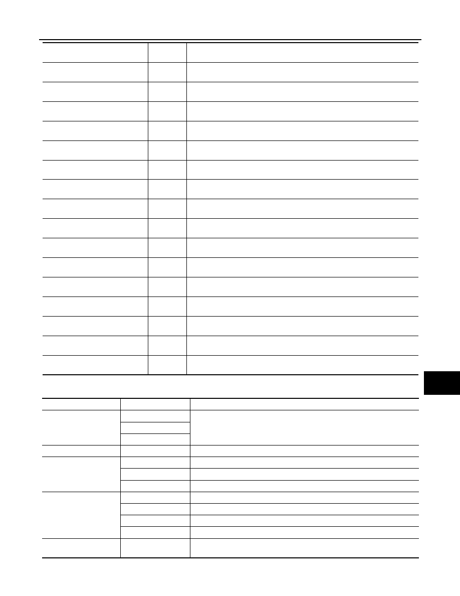
ACTIVE TEST
IGN RLY
[Off/On]
×
Displays the status of the ignition relay judged by IPDM E/R.
PUSH SW
[Off/On]
Displays the status of the push-button ignition switch judged by IPDM E/R.
INTER/NP SW
[Off/On]
Displays the status of the shift position judged by IPDM E/R.
ST RLY CONT
[Off/On]
Displays the status of the starter relay status signal received from BCM via CAN
communication.
IHBT RLY -REQ
[Off/On]
Displays the status of the starter control relay signal received from BCM via CAN
communication.
ST/INHI RLY
[Off/ ST ON/INHI ON/UNKWN]
Displays the status of the starter relay and starter control relay judged by IPDM
E/R.
DETENT SW
[Off/On]
Displays the status of the CVT shift selector (detention switch) judged by IPDM E/
R.
S/L RLY -REQ
[Off/On]
NOTE:
The item is indicated, but not monitored.
S/L STATE
[LOCK/UNLOCK/UNKWN]
NOTE:
The item is indicated, but not monitored.
DTRL REQ
[Off/On]
NOTE:
The item is indicated, but not monitored.
OIL P SW
[Open/Close]
Displays the status of the oil pressure switch judged by IPDM E/R.
HOOD SW
[Off/On]
NOTE:
The item is indicated, but not monitored.
HL WASHER REQ
[Off/On]
NOTE:
The item is indicated, but not monitored.
THFT HRN REQ
[Off/On]
Displays the status of the theft warning horn request signal received from BCM
via CAN communication.
HORN CHIRP
[Off/On]
Displays the status of the horn reminder signal received from BCM via CAN com-
munication.
CRNRNG LMP REQ
[Off/On]
NOTE:
The item is indicated, but not monitored.
Monitor Item
[Unit]
MAIN SIG-
NALS
Description
Test item
Operation
Description
CORNERING LAMP
Off
NOTE:
The item is indicated, but cannot be tested.
LH
RH
HORN
On
Operates horn relay for 20 ms.
FRONT WIPER
Off
OFF
Lo
Operates the front wiper relay.
Hi
Operates the front wiper relay and front wiper high relay.
MOTOR FAN
1
OFF
2
Operates the cooling fan relay-1.
3
Operates the cooling fan relay-2.
4
Operates the cooling fan relay-2 and cooling fan relay-3.
HEAD LAMP WASHER
On
NOTE:
The item is indicated, but cannot be tested.

WW-26
< SYSTEM DESCRIPTION >
DIAGNOSIS SYSTEM (IPDM E/R)
EXTERNAL LAMPS
Off
OFF
TAIL
Operates the tail lamp relay.
Lo
Operates the headlamp low relay.
Hi
Operates the headlamp low relay and ON/OFF the headlamp high relay at 1 sec-
ond intervals.
Fog
Operates the front fog lamp relay.
Test item
Operation
Description
WIPER AND WASHER FUSE, FUSIBLE LINK
WW-27
< DTC/CIRCUIT DIAGNOSIS >
C
D
E
F
G
H
I
J
K
M
A
B
WW
N
O
P
DTC/CIRCUIT DIAGNOSIS
WIPER AND WASHER FUSE, FUSIBLE LINK
Description
INFOID:0000000009719726
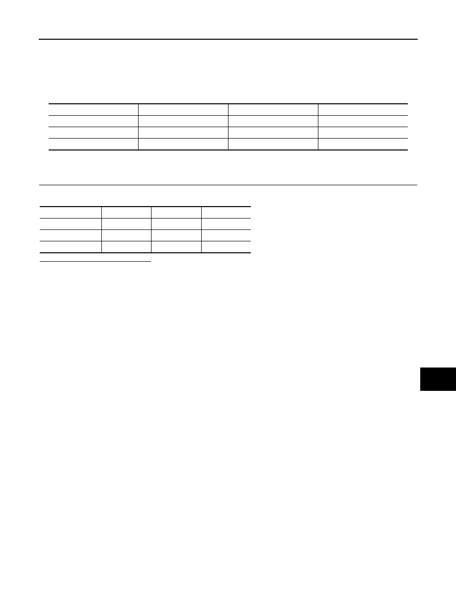
Fuse, fusible link list
Diagnosis Procedure
INFOID:0000000009719727
1.
CHECK FUSES AND FUSIBLE LINK
Check that the following fuses and fusible link are not fusing.
Is the fuse or fusible link fusing?
YES
>> Replace the fuse or fusible link with a new one after repairing the applicable circuit.
NO
>> The fuse or fusible link is normal.
Unit
Location
No.
Capacity
Front wiper motor
IPDM E/R
60
30 A
Washer pump
IPDM E/R
47
10 A
Rain sensor
Fuse block
6
10 A
Unit
Location
No.
Capacity
Front wiper motor
IPDM E/R
60
30 A
Washer pump
IPDM E/R
47
10 A
Rain sensor
Fuse block
6
10 A
Нет комментариевНе стесняйтесь поделиться с нами вашим ценным мнением.
Текст