Nissan Murano. Manual — part 1355
EPS SYSTEM
STC-5
< SYSTEM DESCRIPTION >
C
D
E
F
H
I
J
K
L
M
A
B
STC
N
O
P
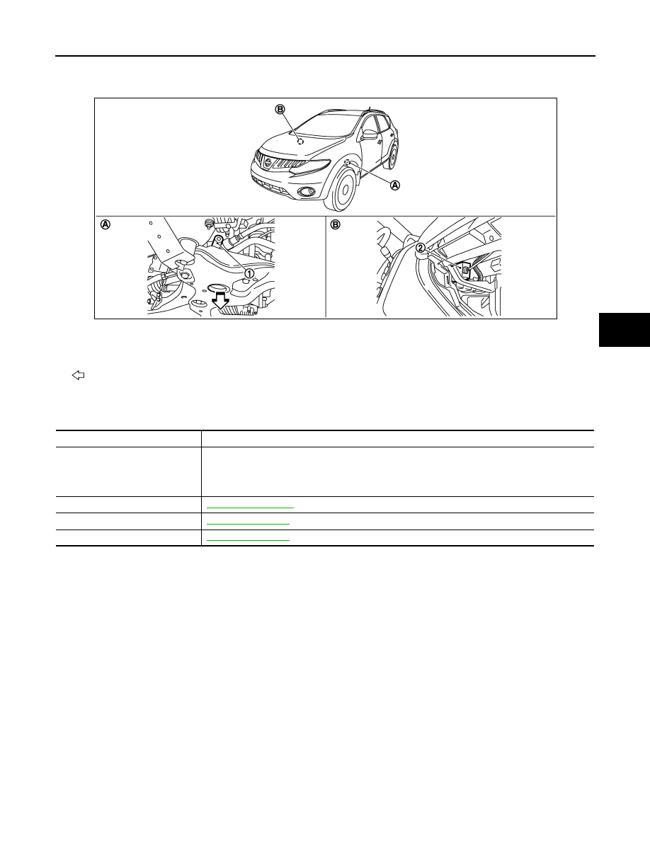
Component Parts Location
INFOID:0000000009722591
Component Description
INFOID:0000000009722592
1.
Power steering solenoid valve
2.
Power steering control unit
A.
Steering gear assembly
B.
Glove box assembly removed
: Vehicle front
JSGIA0301ZZ
Component parts
Reference/Function
Power steering control unit
• Signals from various sensors control the driving voltage to the power steering solenoid valve.
• The power steering control unit controls the driving voltage to the power steering solenoid valve
for maintaining the power steering assist force when the fail-safe function is activated. (The en-
gine speed signals control EPS system if any vehicle speed signal error is detected.)
Combination meter
ECM
Power steering solenoid valve

STC-6
< DTC/CIRCUIT DIAGNOSIS >
POWER SUPPLY AND GROUND CIRCUIT
DTC/CIRCUIT DIAGNOSIS
POWER SUPPLY AND GROUND CIRCUIT
Description
INFOID:0000000009722593
Power supply to EPS system
Diagnosis Procedure
INFOID:0000000009722594
1.
CHECK POWER SUPPLY
1.
Turn the ignition switch OFF.
2.
Disconnect power steering control unit harness connector.
3.
Check voltage between power steering control unit harness connector and ground.
4.
Turn the ignition switch ON.
CAUTION:
Never start the engine.
5.
Check voltage between power steering control unit harness connector and ground.
Is the inspection result normal?
YES
>> GO TO 2.
NO
>>
Check the following. If any items are damaged, repair or replace damaged parts.
• 10A fuses (#3) open
- Harness for short or open between ignition switch and power steering control unit harness con-
nector No. 3 terminal.
- Ignition switch. Refer to
PCS-68, "Component Inspection"
2.
CHECK GROUND CIRCUIT
1.
Turn the ignition switch OFF.
2.
Check continuity between power steering control unit harness connector and ground.
Is the inspection result normal?
YES
>> GO TO 3.
NO
>> Repair open circuit or short to power in harness or connectors.
3.
CHECK TERMINALS AND HARNESS CONNECTORS
Check power steering control unit pin terminals for damage or loose connection with harness connector.
Is the inspection result normal?
YES
>> INSPECTION END
NO
>> Repair or replace damaged parts.
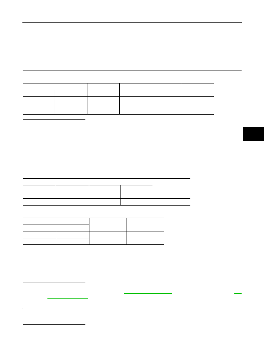
Power steering control unit
—
Voltage
(Approx.)
Connector
Terminal
M61
3 Ground
0
V
Power steering control unit
—
Voltage
(Approx.)
Connector
Terminal
M61
3 Ground
Battery
voltage
Power steering control unit
—
Continuity
Connector
Terminal
M61
6 Ground
Existed
POWER STEERING SOLENOID VALVE
STC-7
< DTC/CIRCUIT DIAGNOSIS >
C
D
E
F
H
I
J
K
L
M
A
B
STC
N
O
P
POWER STEERING SOLENOID VALVE
Description
INFOID:0000000009722595
Power steering solenoid valve controls the power steering oil pressure in the gear housing assembly.
Diagnosis Procedure
INFOID:0000000009722596
1.
CHECK POWER STEERING SOLENOID VALVE SIGNAL
Check voltage between power steering control unit harness connector and ground.
Is the inspection result normal?
YES
>> GO TO 4.
NO
>> GO TO 2.
2.
CHECK HARNESS BETWEEN POWER STEERING SOLENOID VALVE AND POWER STEERING CON-
TROL UNIT
1.
Turn the ignition switch OFF.
2.
Disconnect power steering solenoid valve harness connector.
3.
Disconnect power steering control unit harness connector.
4.
Check the continuity between power steering solenoid valve harness connector and the power steering
control unit harness connector.
5.
Check continuity between power steering control unit harness connector and ground.
Is the inspection result normal?
YES
>> GO TO 3.
NO
>> Repair or replace damaged parts.
3.
CHECK POWER STEERING SOLENOID VALVE
Check power steering solenoid valve. Refer to
.
Is the inspection result normal?
YES
>> GO TO 4.
NO
>> Replace gear-sub assembly. Refer to
(With heated steering wheel),
(Without heated steering wheel).
4.
CHECK TERMINALS AND HARNESS CONNECTORS
• Check power steering control unit pin terminals for damage or loose connection with harness connector.
• Check power steering solenoid valve pin terminals for damage or loose connection with harness connector.
Is the inspection result normal?
Power steering control unit
—
Condition
Voltage
(Approx.)
Connector
Terminal
M61
1
Ground
Vehicle speed: 0 km/h (0 MPH)
(Engine is running)
4.4 – 6.6 V
Vehicle speed: 100 km/h (62 MPH)
2.4 – 3.6 V
Power steering solenoid valve
Power steering control unit
Continuity
Connector
Terminal
Connector
Terminal
E52
1
M61
1
Existed
E52
2
M61
5
Existed
Power steering control unit
—
Continuity
Connector
Terminal
M61
1
Ground
Not existed
M61
5
STC-8
< DTC/CIRCUIT DIAGNOSIS >
POWER STEERING SOLENOID VALVE
YES
>> INSPECTION END
NO
>> Repair or replace damaged parts.
Component Inspection
INFOID:0000000009722597
1.
CHECK POWER STEERING SOLENOID VALVE
1.
Turn the ignition switch OFF.
2.
Disconnect power steering solenoid valve harness connector.
3.
Check resistance between power steering solenoid valve connector terminals.
4.
Check power steering solenoid valve by listening for its operation sound while applying battery voltage to
power steering solenoid valve connector E52 terminals 1 (positive) and 2 (negative).
Is the inspection result normal?
YES
>> INSPECTION END
NO
>> Replace gear-sub assembly. Refer to
(Without heated steering wheel).
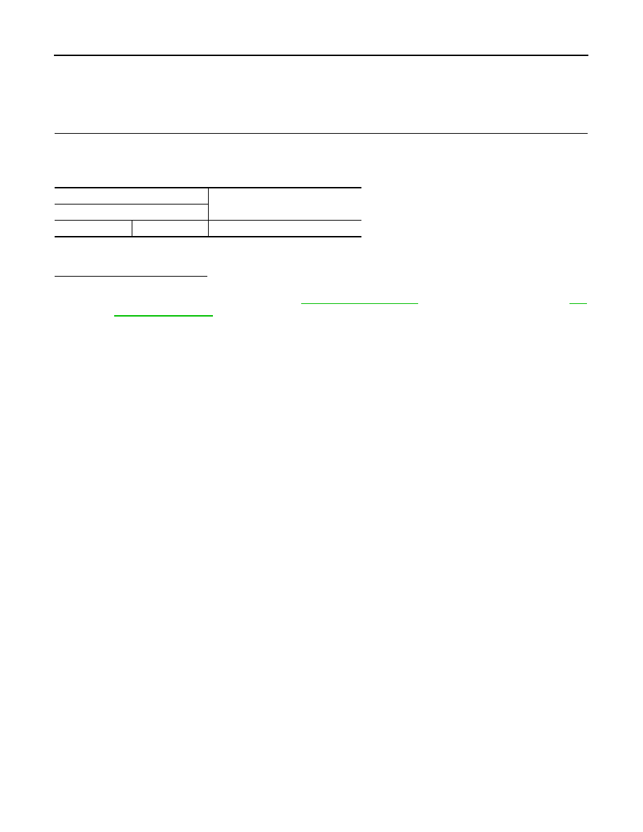
Power steering solenoid valve
Resistance (Approx.)
Terminal
1 2
4
–
6
Ω
Нет комментариевНе стесняйтесь поделиться с нами вашим ценным мнением.
Текст