Nissan Murano. Manual — part 1437

VTL-104
< REMOVAL AND INSTALLATION >
[WITH 7 INCH DISPLAY]
HEATER & COOLING UNIT ASSEMBLY
15. Remove rear foot ducts 1 (A) and rear ventilator duct 1 (B), and
then remove heater & cooling unit assembly (1).
INSTALLATION
Note the following items and then install in the reverse order of removal.
CAUTION:
• Replace the O-ring with a new one. Apply a coat of compressor oil to the O-ring prior to installation.
• Check for refrigerant leakage when charging refrigerant.
NOTE:
• Refer to
when filling the radiator with engine coolant.
• Charge the refrigerant again.
JPIIA0573ZZ
UPPER VENTILATOR DOOR MOTOR
VTL-105
< REMOVAL AND INSTALLATION >
[WITH 7 INCH DISPLAY]
C
D
E
F
G
H
J
K
L
M
A
B
VTL
N
O
P
UPPER VENTILATOR DOOR MOTOR
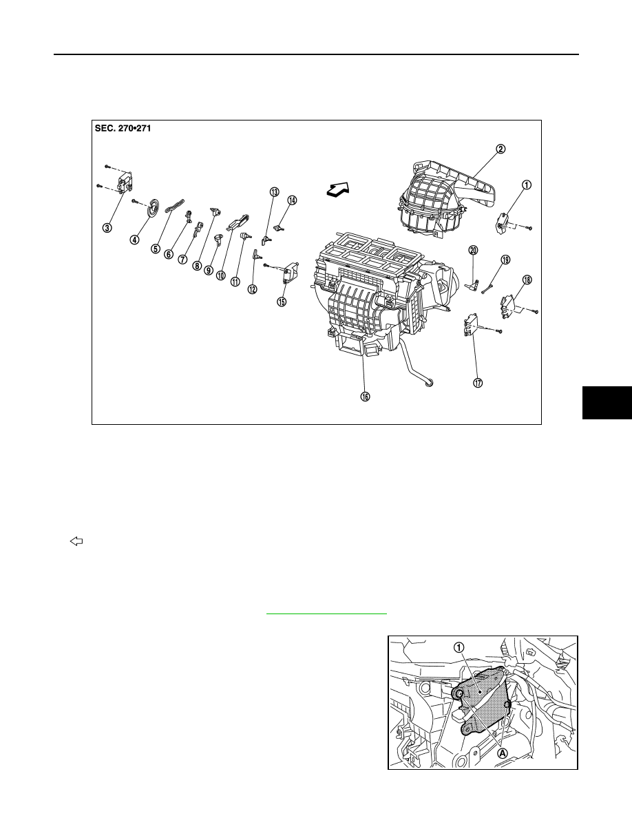
Exploded View
INFOID:0000000009721177
Removal and Installation
INFOID:0000000009721178
REMOVAL
1.
Remove blower unit assembly. Refer to
.
2.
Disconnect upper ventilator door motor connector.
3.
Remove fixing screws (A) and then remove upper ventilator
door motor (1).
INSTALLATION
1.
Intake door motor
2.
Bower unit assembly
3.
Mode door motor
4.
Main link
5.
Rod link
6.
Max. cool door link
7.
Max. cool door link
8.
Mode door lever
9.
Ventilator door link
10. Defroster door link
11.
Ventilator door lever
12. Foot door lever
13. Max. cool door lever
14.
Defroster door lever
15. Air mix door motor (Driver side)
16. Heater & cooling unit assembly
17.
Air mix door motor (Passenger side) 18. Upper ventilator door motor
19. Upper ventilator door rod
20.
Upper ventilator door lever
: Vehicle front
JPIIA1238ZZ
JPIIA0574ZZ
VTL-106
< REMOVAL AND INSTALLATION >
[WITH 7 INCH DISPLAY]
UPPER VENTILATOR DOOR MOTOR
Install in the reverse order of removal.
MODE DOOR MOTOR
VTL-107
< REMOVAL AND INSTALLATION >
[WITH 7 INCH DISPLAY]
C
D
E
F
G
H
J
K
L
M
A
B
VTL
N
O
P
MODE DOOR MOTOR
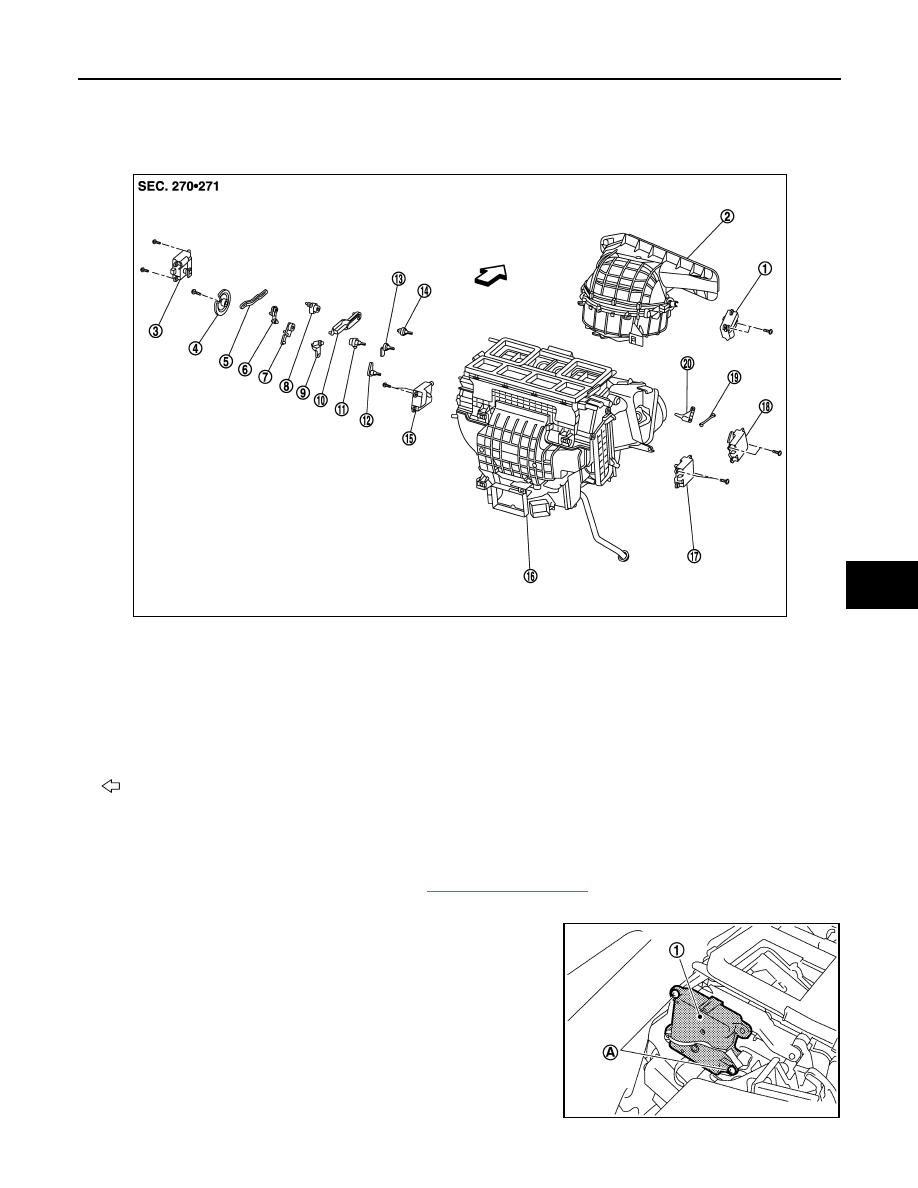
Exploded View
INFOID:0000000009721179
Removal and Installation
INFOID:0000000009721180
REMOVAL
1.
Remove instrument panel assembly. Refer to
.
2.
Disconnect mode door motor connector.
3.
Remove fixing screws (A) and then remove mode door motor
(1).
INSTALLATION
1.
Intake door motor
2.
Bower unit assembly
3.
Mode door motor
4.
Main link
5.
Rod link
6.
Max. cool door link
7.
Max. cool door link
8.
Mode door lever
9.
Ventilator door link
10. Defroster door link
11.
Ventilator door lever
12. Foot door lever
13. Max. cool door lever
14.
Defroster door lever
15. Air mix door motor (Driver side)
16. Heater & cooling unit assembly
17.
Air mix door motor (Passenger side) 18. Upper ventilator door motor
19. Upper ventilator door rod
20.
Upper ventilator door lever
: Vehicle front
JPIIA1238ZZ
JPIIA0575ZZ
Нет комментариевНе стесняйтесь поделиться с нами вашим ценным мнением.
Текст