Nissan Murano. Manual — part 628
EM-86
< UNIT REMOVAL AND INSTALLATION >
ENGINE ASSEMBLY
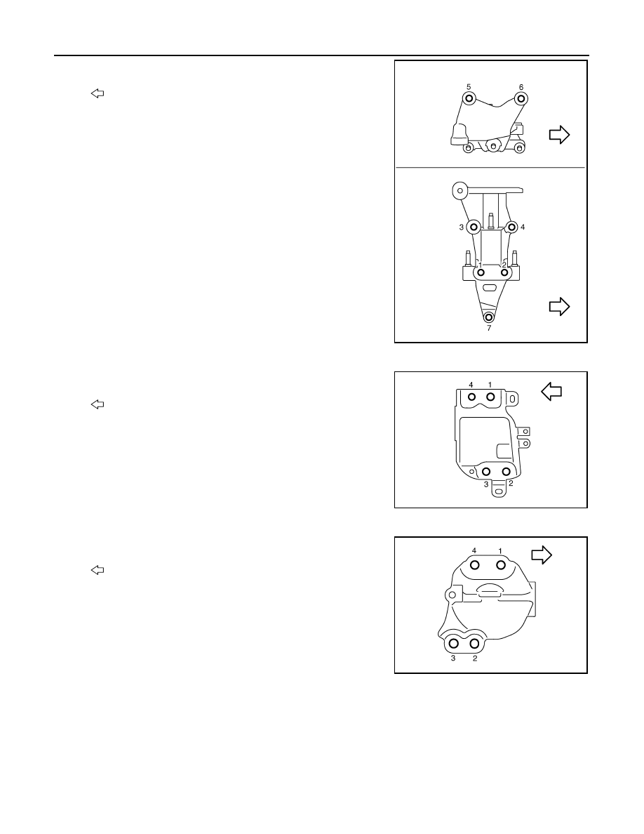
a.
Tighten the bolt No. 7 as shown in the figure. (temporarily)
b.
Tighten the bolts in numerical order as shown in the figure.
(specified torque)
2.
Install the engine mounting bracket (front) to the engine as follows:
a.
Tighten the bolt No. 4 as shown in the figure. (temporarily)
b.
Tighten the bolts in numerical order as shown in the figure.
(specified torque)
3.
Install the engine mounting bracket (rear) to the engine as follows:
a.
Tighten the bolt No. 4 as shown in the figure. (temporarily)
b.
Tighten the bolts in numerical order as shown in the figure.
(specified torque)
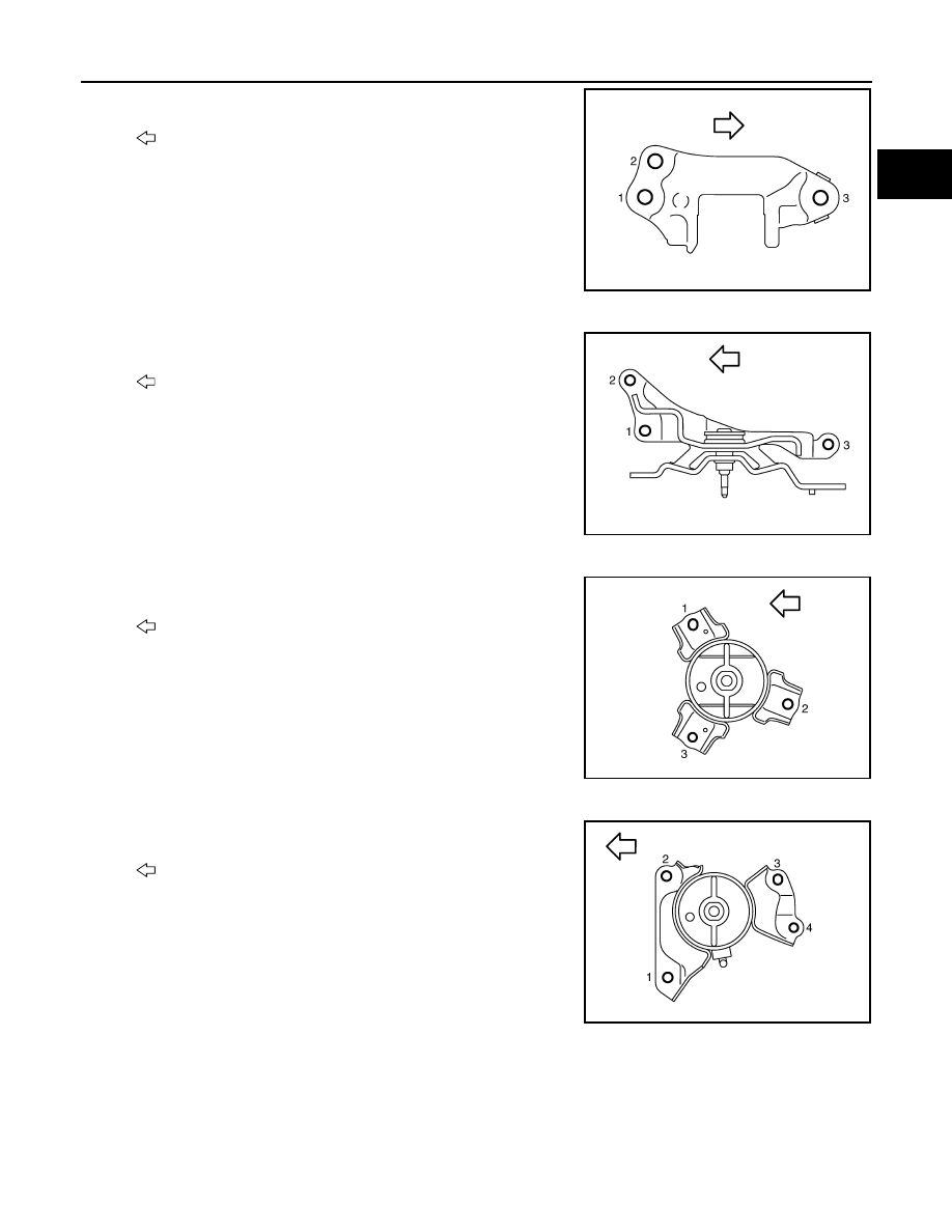
4.
Install the rear torque rod bracket to the engine as follows:
: Vehicle front
JPBIA1730ZZ
: Engine front
JPBIA1744ZZ
: Engine front
JPBIA1745ZZ
ENGINE ASSEMBLY
EM-87
< UNIT REMOVAL AND INSTALLATION >
C
D
E
F
G
H
I
J
K
L
M
A
EM
N
P
O
a.
Tighten the bolt No. 3 as shown in the figure. (temporarily)
b.
Tighten the bolts in numerical order as shown in the figure.
(specified torque)
5.
Install the engine mounting insulator (LH) to the transaxle as follows:
a.
Tighten the bolt No. 3 as shown in the figure. (temporarily)
b.
Tighten the bolts in numerical order as shown in the figure.
(specified torque)
6.
Install the engine mounting insulator (front) to the front suspension member as follows:
a.
Tighten the bolt No. 3 as shown in the figure. (temporarily)
b.
Tighten the bolts in numerical order as shown in the figure.
(specified torque)
7.
Install the engine mounting insulator (rear) to the front suspension member as follows:
a.
Tighten the bolt No. 4 as shown in the figure. (temporarily)
b.
Tighten the bolts in numerical order as shown in the figure.
(specified torque)
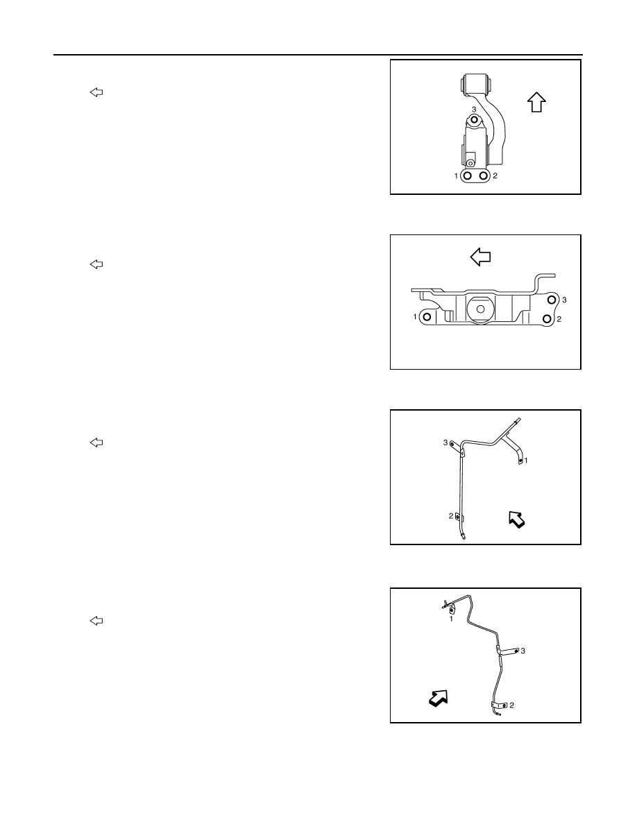
8.
Install the rear torque rod to the front suspension member as follows:
: Engine front
JPBIA1733ZZ
: Vehicle front
JPBIA1734ZZ
: Vehicle front
JPBIA1735ZZ
: Vehicle front
JPBIA1746ZZ
EM-88
< UNIT REMOVAL AND INSTALLATION >
ENGINE ASSEMBLY
a.
Tighten the bolt No. 3 as shown in the figure. (temporarily)
b.
Tighten the bolts in numerical order as shown in the figure.
(specified torque)
9.
Install the engine mounting brackets (front and rear) to the engine mounting insulators (front and rear).
10. Install the engine mounting insulator (LH) to the front suspension member.
• Tighten the bolts in numerical order as shown in the figure.
11. Install the rear torque rod to the rear torque rod bracket.
12. Install the vacuum tube (front) as follows:
a.
Tighten the bolt No. 3 as shown in the figure. (temporarily)
b.
Tighten the bolts in numerical order as shown in the figure.
(specified torque)
With vacuum tube (rear) models
13. Install the vacuum tube (rear) as follows:
a.
Tighten the bolt No. 3 as shown in the figure. (temporarily)
b.
Tighten the bolts in numerical order as shown in the figure.
(specified torque)
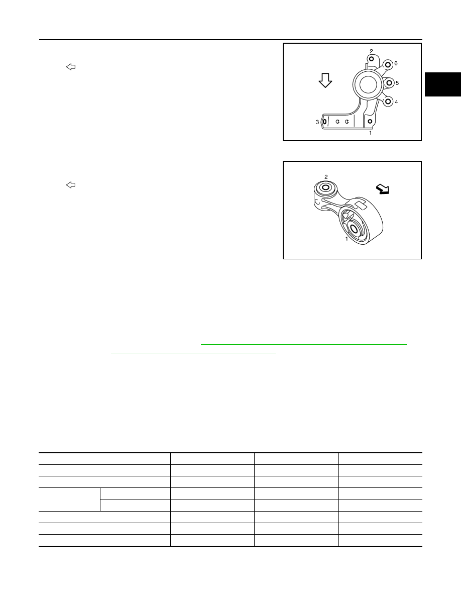
Installation
1.
Install the engine mounting insulator (RH) as follows:
: Vehicle front
JPBIA1738ZZ
: Vehicle front
JPBIA1739ZZ
: Engine front
JPBIA1740ZZ
: Engine front
JPBIA1747ZZ
ENGINE ASSEMBLY
EM-89
< UNIT REMOVAL AND INSTALLATION >
C
D
E
F
G
H
I
J
K
L
M
A
EM
N
P
O
a.
Tighten the bolt No. 1 as shown in the figure. (temporarily)
b.
Tighten the bolts No. 2, 3 in numerical order as shown in the fig-
ure. (specified torque)
c.
Tighten the bolt No. 1 as shown in the figure. (specified torque)
d.
Tighten the bolts No. 4, 5, 6 in numerical order as shown in the
figure. (specified torque)
2.
Install the upper torque rod as follows:
a.
Tighten the bolt No. 2 as shown in the figure. (temporarily)
b.
Tighten the bolts in numerical order as shown in the figure.
(specified torque)
AWD : Inspection
INFOID:0000000009717990
INSPECTION AFTER INSTALLATION
Inspection for Leakage
The following are procedures for checking fluids leakage, lubricates leakage, and exhaust gases leakage.
• Before starting engine, check oil/fluid levels including engine coolant and engine oil. If less than required
quantity, fill to the specified level. Refer to
MA-15, "FOR NORTH AMERICA : Fluids and Lubricants"
(for
North America) or
MA-16, "FOR MEXICO : Fluids and Lubricants"
• Use procedure below to check for fuel leakage.
- Turn ignition switch “ON” (with engine stopped). With fuel pressure applied to fuel piping, check for fuel leak-
age at connection points.
- Start engine. With engine speed increased, check again for fuel leakage at connection points.
• Run engine to check for unusual noise and vibration.
• Warm up engine thoroughly to check there is no leakage of fuel, exhaust gases, or any oil/fluids including
engine oil and engine coolant.
• Bleed air from lines and hoses of applicable lines, such as in cooling system.
• After cooling down engine, again check oil/fluid levels including engine oil and engine coolant. Refill to the
specified level, if necessary.
Summary of the inspection items:
*: Power steering fluid, brake fluid, etc.
: Vehicle front
JPBIA1742ZZ
: Vehicle front
JPBIA1743ZZ
Items
Before starting engine
Engine running
After engine stopped
Engine coolant
Level
Leakage
Level
Engine oil
Level
Leakage
Level
Transmission /
transaxle fluid
AT & CVT Models
Leakage
Level / Leakage
Leakage
MT Models
Level / Leakage
Leakage
Level / Leakage
Other oils and fluids*
Level
Leakage
Level
Fuel
Leakage
Leakage
Leakage
Exhaust gases
—
Leakage
—
Нет комментариевНе стесняйтесь поделиться с нами вашим ценным мнением.
Текст