Nissan Murano. Manual — part 107
AV-206
< ECU DIAGNOSIS INFORMATION >
[BOSE AUDIO WITHOUT NAVIGATION]
SATELLITE RADIO TUNER
SATELLITE RADIO TUNER
Reference Value
INFOID:0000000009721728
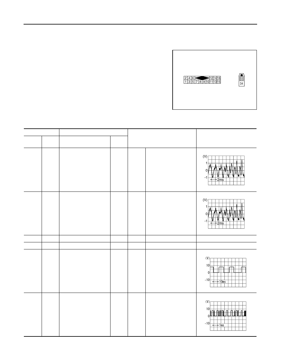
TERMINAL LAYOUT
PHYSICAL VALUES
JPNIA0010ZZ
Terminal
Description
Condition
Reference value
(Approx.)
+
–
Signal name
Input/
Output
2
(Y/L)
1
(W/L)
Satellite radio sound signal
LH
Output
Ignition
switch
ON
When satellite radio mode
is selected.
4
(BR/L)
3
(Y/G)
Satellite radio sound signal
RH
Output
Ignition
switch
ON
When satellite radio mode
is selected
5
—
Shield
—
—
—
—
6
—
Shield
—
—
—
—
8
(R/W)
Ground
Request signal
(SAT
→
CONT)
Output
Ignition
switch
ON
When satellite radio mode
is selected
9
(R/L)
Ground
Communication signal
(SAT
→
CONT)
Output
Ignition
switch
ON
When satellite radio mode
is selected
SKIB3609E
SKIB3609E
SKIA9299J
SKIA9300J

AV
SATELLITE RADIO TUNER
AV-207
< ECU DIAGNOSIS INFORMATION >
[BOSE AUDIO WITHOUT NAVIGATION]
C
D
E
F
G
H
I
J
K
L
M
B
A
O
P
10
(B)
Ground
Communication signal
(CONT
→
SAT)
Input
Ignition
switch
ON
When satellite radio mode
is selected
12
(V)
Ground
Battery power supply
Input
Ignition
switch
OFF
—
Battery voltage
15
(B)
Ground
Ground
—
Ignition
switch
ON
—
0 V
16
(GR)
Ground
ACC power supply
Input
Ignition
switch
ACC
—
Battery voltage
33
—
Satellite radio antenna sig-
nal
Input
—
—
—
Terminal
Description
Condition
Reference value
(Approx.)
+
–
Signal name
Input/
Output
SKIA9301J
AV-208
< ECU DIAGNOSIS INFORMATION >
[BOSE AUDIO WITHOUT NAVIGATION]
TEL ADAPTER UNIT
TEL ADAPTER UNIT
Reference Value
INFOID:0000000009721729
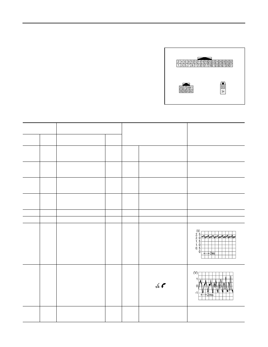
TERMINAL LAYOUT
PHYSICAL VALUES
JPNIA0011ZZ
Terminal
(Wire color)
Description
Condition
Reference value
(Approx.)
+
–
Signal name
Input/
Output
1
(V)
Ground
Battery power supply
Input
Ignition
switch
OFF
—
Battery voltage
2
(GR)
Ground
ACC power supply
Input
Ignition
switch
ACC
—
Battery voltage
3
(R)
Ground
Ignition signal
Input
Ignition
switch
ON
—
Battery voltage
4
(B/W)
Ground
Ground
—
Ignition
switch
ON
—
0 V
5
—
Shield
—
—
—
—
6
—
Shield
—
—
—
—
7
(R/W)
8
(R/L)
Microphone signal
Input
Ignition
switch
ON
Give a voice
9
(B/R)
10
(W/R)
TEL voice signal
Output
Ignition
switch
ON
During voice guide output
with
the
switch
pressed.
20
(B)
Ground
Control signal
Input
Ignition
switch
ON
—
0 V
PKIB5037J
SKIB3609E
AV
TEL ADAPTER UNIT
AV-209
< ECU DIAGNOSIS INFORMATION >
[BOSE AUDIO WITHOUT NAVIGATION]
C
D
E
F
G
H
I
J
K
L
M
B
A
O
P
24
(B/W)
Ground
Control signal
Input
Ignition
switch
ON
—
0 V
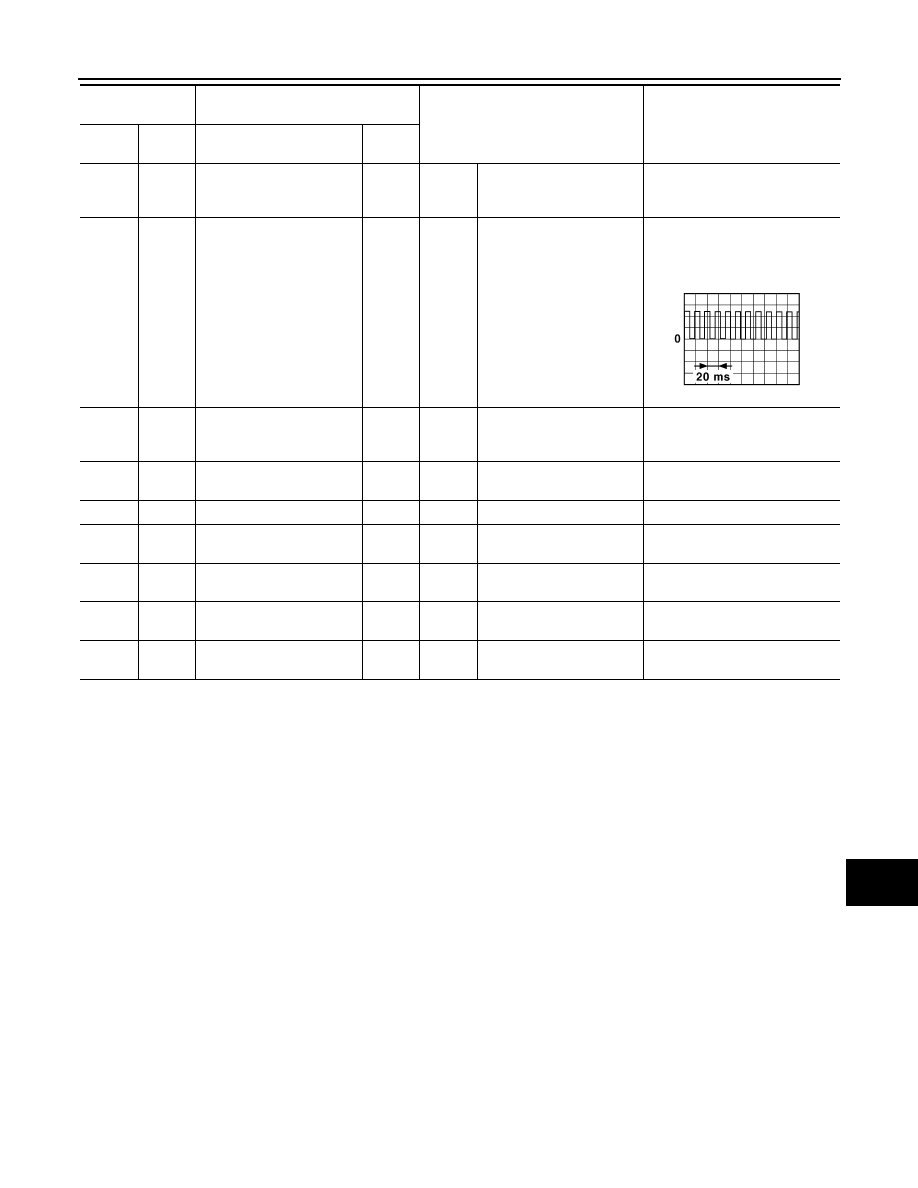
28
(BR)
Ground
Vehicle speed signal
(8-pulse)
Input
Ignition
switch
ON
When vehicle speed is ap-
prox. 40 km/h (25 MPH)
NOTE:
The maximum voltage varies de-
pending on the specification
(destination unit).
29
(B)
8
(R/L)
Microphone VCC
Output
Ignition
switch
ON
—
5.0 V
33
—
TEL antenna signal
Input/
Output
—
—
—
34
—
Shield
—
—
—
—
35
(SB)
—
AV communication signal
(H)
Input/
Output
—
—
—
36
(LG)
—
AV communication signal
(L)
Input/
Output
—
—
—
40
(G)
—
AV communication signal
(H)
Input/
Output
—
—
—
42
(GR)
—
AV communication signal
(L)
Input/
Output
—
—
—
Terminal
(Wire color)
Description
Condition
Reference value
(Approx.)
+
–
Signal name
Input/
Output
JSNIA0012GB
Нет комментариевНе стесняйтесь поделиться с нами вашим ценным мнением.
Текст