Nissan Murano. Manual — part 1123
PWC-30
< DTC/CIRCUIT DIAGNOSIS >
ENCODER CIRCUIT
2.
Disconnect front power window switch (passenger side) connector and front power window motor (pas-
senger side) connector.
3.
Check continuity between front power window switch (passenger side) harness connector and front power
window motor (passenger side) harness connector.
4.
Check continuity between front power window switch (passenger side) harness connector and ground.
Is the inspection result normal?
YES
>> GO TO 3.
NO
>> Repair or replace harness.
3.
CHECK ENCORDER POWER SUPPLY
1.
Connect front power window switch (passenger side) connector.
2.
Turn ignition switch ON.
3.
Check voltage between front power window motor (passenger side) harness connector and ground.
Is the inspection result normal?
YES
>> GO TO 5.
NO
>> GO TO 4.
4.
CHECK ENCODER POWER SUPPLY CIRCUIT
1.
Turn ignition switch OFF.
2.
Disconnect front power window switch (passenger side) connector.
3.
Check continuity between front power window switch (passenger side) harness connector and front power
window motor (passenger side) harness connector.
4.
Check continuity between front power window switch (passenger side) harness connector and ground.
Is the inspection result normal?
YES
>> Replace front power window switch (passenger side). Refer to
PWC-118, "Removal and Installa-
.
NO
>> Repair or replace harness.
5.
CHECK GROUND CIRCUIT 1
1.
Turn ignition switch OFF.
Front power window switch (passenger side)
Front power window motor (passenger side)
Continuity
Connector
Terminal
Connector
Terminal
D45
12
D46
5
Existed
15
3
Front power window switch (passenger side)
Ground
Continuity
Connector
Terminal
D45
12
Not existed
15
(+)
(–)
Voltage (V)
(Approx.)
Front power window motor (passenger side)
Connector
Terminal
D46
4
Ground
Battery voltage
Front power window switch (passenger side)
Front power window motor (passenger side)
Continuity
Connector
Terminal
Connector
Terminal
D45
4
D46
4
Existed
Front power window switch (passenger side)
Ground
Continuity
Connector
Terminal
D45
4
Not existed
ENCODER CIRCUIT
PWC-31
< DTC/CIRCUIT DIAGNOSIS >
C
D
E
F
G
H
I
J
L
M
A
B
PWC
N
O
P
2.
Disconnect front power window switch (passenger side) connector.
3.
Check continuity between front power window switch (passenger side) harness connector and front power
window motor (passenger side) harness connector.
Is the inspection result normal?
YES
>> GO TO 6.
NO
>> Repair or replace harness.
6.
CHECK GROUND CIRCUIT 2
1.
Connect front power window switch (passenger side) connector.
2.
Check continuity between front power window switch (passenger side) harness connector and ground.
Is the inspection result normal?
YES
>> Replace front power window motor (passenger side). Refer to
GW-22, "Removal and Installation"
.
NO
>> Replace front power window switch (passenger side). Refer to
PWC-118, "Removal and Installa-
.
Front power window switch (passenger side)
Front power window motor (passenger side)
Continuity
Connector
Terminal
Connector
Terminal
D45
3
D46
6
Existed
Front power window switch (passenger side)
Ground
Continuity
Connector
Terminal
D45
3
Existed
PWC-32
< DTC/CIRCUIT DIAGNOSIS >
POWER WINDOW SERIAL LINK
POWER WINDOW SERIAL LINK
POWER WINDOW MAIN SWITCH
POWER WINDOW MAIN SWITCH : Description
INFOID:0000000009723155
Power window main switch, front power window switch (passenger side) and BCM transmit and receive the
signal by power window serial link.
The signal mentioned below is transmitted from BCM to power window main switch, front power window
switch (passenger side).
• Keyless power window down signal
The signal mentioned below is transmitted from power window main switch to front power window switch (pas-
senger side).
• Front passenger side door window operation signal
• Power window control by key cylinder switch signal
• Power window lock switch signal
• Retained power operation signal
POWER WINDOW MAIN SWITCH : Component Function Check
INFOID:0000000009723156
1.
CHECK POWER WINDOW SWITCH OUTPUT SIGNAL
With CONSULT
Check (“CDL LOCK SW ”, “CDL UNLOCK SW”) in “DATA MONITOR” mode for “POWER DOOR LOCK SYS-
TEM” with CONSULT. Refer to
DLK-55, "DOOR LOCK : CONSULT Function (BCM - DOOR LOCK)"
Is the inspection result normal?
YES
>> Power window serial link is OK.
NO
>> Refer to
PWC-32, "POWER WINDOW MAIN SWITCH : Diagnosis Procedure"
POWER WINDOW MAIN SWITCH : Diagnosis Procedure
INFOID:0000000009723157
1.
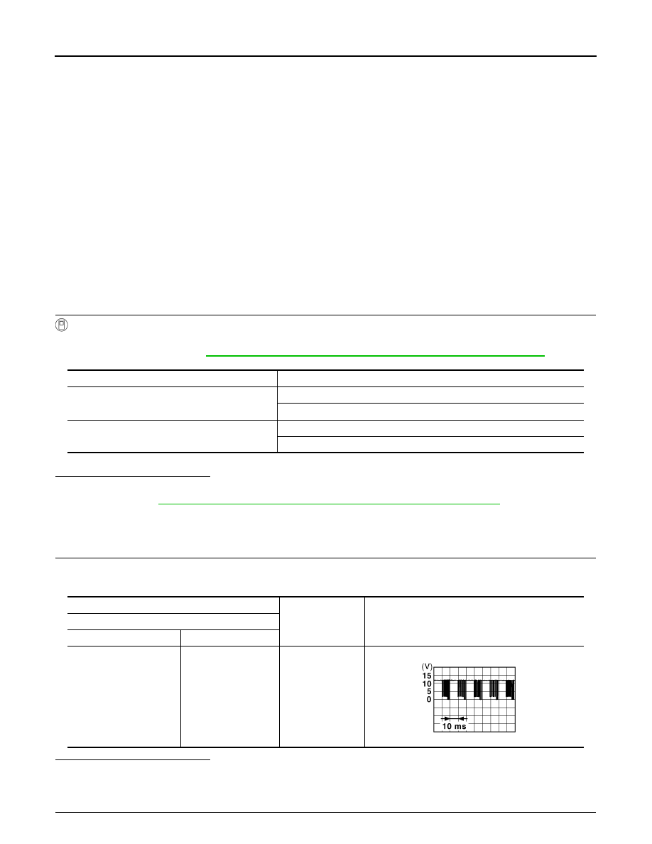
CHECK POWER WINDOW SWITCH OUTPUT SIGNAL
1.
Turn ignition switch ON.
2.
Check signal between power window main switch harness connector and ground.
Is the inspection result normal?
YES
>> GO TO 4.
NO
>> GO TO 2.
2.
CHECK POWER WINDOW SERIAL LINK SIGNAL
Monitor item
Condition
CDL LOCK SW
LOCK
: ON
UNLOCK
: OFF
CDL UNLOCK SW
LOCK
: OFF
UNLOCK
: ON
(+)
(–)
Signal
(Reference value)
Power window main switch
Connector
Terminal
D5
14
Ground
JPMIA0013GB
POWER WINDOW SERIAL LINK
PWC-33
< DTC/CIRCUIT DIAGNOSIS >
C
D
E
F
G
H
I
J
L
M
A
B
PWC
N
O
P
1.
Turn ignition switch OFF.
2.
Disconnect power window main switch connector.
3.
Turn ignition switch ON.
4.
Check voltage between power window main switch harness connector and ground.
Is the measurement value within the specification?
YES
>> Replace power window main switch. Refer to
PWC-118, "Removal and Installation"
.
NO
>> GO TO 3.
3.
CHECK POWER WINDOW SERIAL LINK CIRCUIT
1.
Turn ignition switch OFF.
2.
Disconnect BCM connector.
3.
Check continuity between BCM connector and power window main switch connector.
4.
Check continuity between BCM connector and ground.
Is the inspection result normal?
YES
>> Replace BCM. Refer to
.
NO
>> Repair or replace harness.
4.
CHECK INTERMITTENT INCIDENT
GI-44, "Intermittent Incident"
.
>> INSPECTION END
FRONT POWER WINDOW SWITCH (PASSENGER SIDE)
FRONT POWER WINDOW SWITCH (PASSENGER SIDE) : Description
INFOID:0000000009723158
Power window main switch, front power window switch (passenger side) and BCM transmit and receive the
signal by power window serial link.
The signal mentioned below is transmitted from BCM to power window main switch, front power window
switch (passenger side).
• Keyless power window down signal
The signal mentioned below is transmitted from power window main switch to front power window switch (pas-
senger side).
• Front passenger side door window operation signal
• Power window control by key cylinder switch signal
• Power window lock switch signal
• Retained power operation signal
FRONT POWER WINDOW SWITCH (PASSENGER SIDE) : Component Function
Check
INFOID:0000000009723159
1.
CHECK POWER WINDOW SWITCH OUTPUT SIGNAL
(+)
(–)
Voltage (V)
(Approx.)
Power window main switch
Connector
Terminal
D5
14
Ground
Battery voltage
BCM
Power window main switch
Continuity
Connector
Terminal
Connector
Terminal
M123
132
D5
14
Existed
BCM
Ground
Continuity
Connector
Terminal
M123
132
Not existed
Нет комментариевНе стесняйтесь поделиться с нами вашим ценным мнением.
Текст