Nissan Murano. Manual — part 213
BRC-8
< BASIC INSPECTION >
[VDC/TCS/ABS]
DIAGNOSIS AND REPAIR WORK FLOW
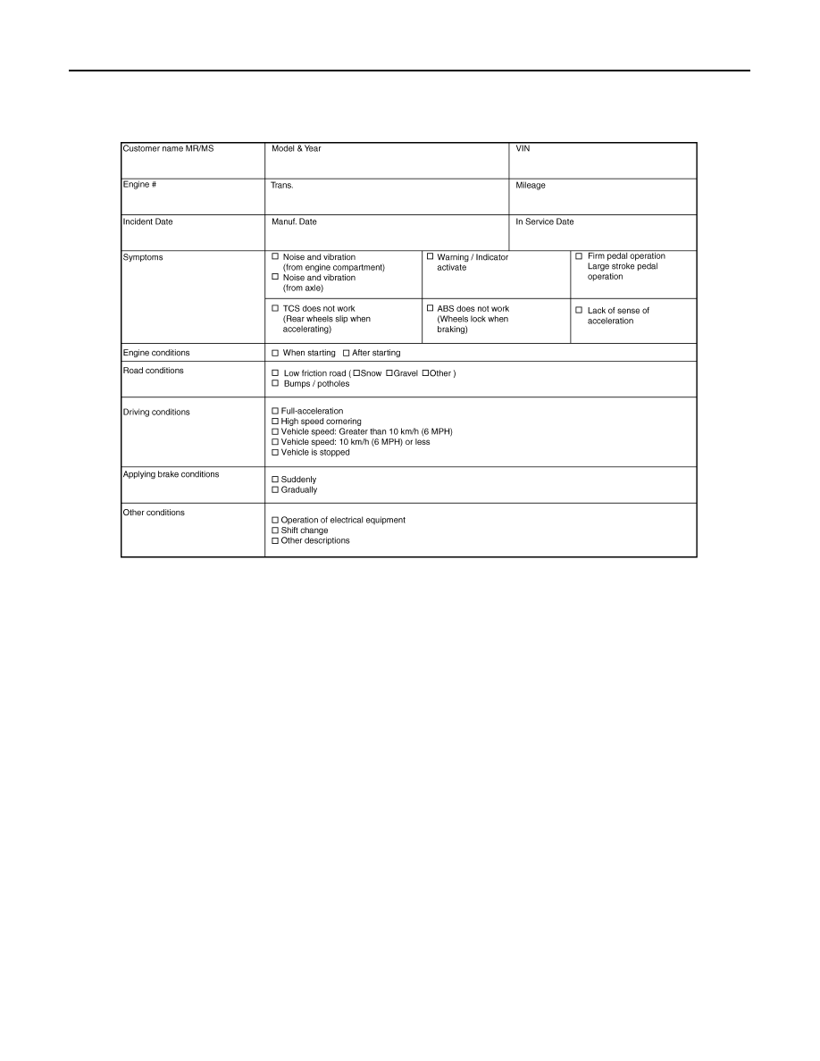
Diagnostic Work Sheet
INFOID:0000000009718212
SFIA3265E

INSPECTION AND ADJUSTMENT
BRC-9
< BASIC INSPECTION >
[VDC/TCS/ABS]
C
D
E
G
H
I
J
K
L
M
A
B
BRC
N
O
P
INSPECTION AND ADJUSTMENT
ADDITIONAL SERVICE WHEN REPLACING CONTROL UNIT
ADDITIONAL SERVICE WHEN REPLACING CONTROL UNIT : Description
INFOID:0000000009718213
Perform the steering angle sensor adjustment and decel G sensor calibration after replacing the ABS actuator
and electric unit (control unit).
ADDITIONAL SERVICE WHEN REPLACING CONTROL UNIT : Special Repair Re-
quirement
INFOID:0000000009718214
1.
PERFORM ADJUSTMENT OF STEERING ANGLE SENSOR AND CALIBRATION OF DECEL G SENSOR
Perform steering angle sensor adjustment and decel G sensor calibration.
• Adjustment of steering angle sensor: Refer to
BRC-9, "ADJUSTMENT OF STEERING ANGLE SENSOR
NEUTRAL POSITION : Description"
• Calibration of decel G sensor: Refer to
BRC-10, "CALIBRATION OF DECEL G SENSOR : Description"
.
>> INSPECTION END
ADJUSTMENT OF STEERING ANGLE SENSOR NEUTRAL POSITION
ADJUSTMENT OF STEERING ANGLE SENSOR NEUTRAL POSITION : Description
INFOID:0000000009718215
When doing work that applies to the list below, make sure to adjust neutral position of steering angle sensor
before running vehicle.
×
: Required –: Not required
ADJUSTMENT OF STEERING ANGLE SENSOR NEUTRAL POSITION : Special Re-
pair Requirement
INFOID:0000000009718216
ADJUSTMENT OF STEERING ANGLE SENSOR NEUTRAL POSITION
CAUTION:
To adjust neutral position of steering angle sensor, make sure to use CONSULT.
(Adjustment cannot be done without CONSULT.)
1.
ALIGN THE VEHICLE STATUS
Stop the vehicle with front wheels in straight-ahead position.
>> GO TO 2.
2.
PERFORM THE NEUTRAL POSITION ADJUSTMENT FOR THE STEERING ANGLE SENSOR
Situation
Adjustment of steering angle sensor neutral position
Removing/Installing ABS actuator and electric unit (control unit)
—
Replacing ABS actuator and electric unit (control unit)
×
Removing/Installing steering angle sensor
×
Replacing steering angle sensor
×
Removing/Installing steering components
×
Replacing steering components
×
Removing/Installing suspension components
×
Replacing suspension components
×
Change tires to new ones
—
Tire rotation
—
Adjusting wheel alignment
×

BRC-10
< BASIC INSPECTION >
[VDC/TCS/ABS]
INSPECTION AND ADJUSTMENT
1.
Select “ABS”, “WORK SUPPORT” and “ST ANGLE SENSOR ADJUSTMENT” in order with CONSULT.
2.
Select “START”.
CAUTION:
Never touch steering wheel while adjusting steering angle sensor.
3.
After approximately 10 seconds, select “END”.
NOTE:
After approximately 60 seconds, it ends automatically.
4.
Turn the ignition switch OFF, then turn it ON again.
CAUTION:
Be sure to perform above operation.
>> GO TO 3.
3.
CHECK DATA MONITOR
1.
Run the vehicle with front wheels in straight-ahead position, then stop.
2.
Select “ABS”, “DATA MONITOR” and “STR ANGLE SIG” in order with CONSULT, and check the steering
angle sensor signal.
Is the steering angle within the specified range?
YES
>> GO TO 4.
NO
>> Perform the neutral position adjustment for the steering angle sensor again, GO TO 1.
4.
ERASE THE SELF-DIAGNOSIS MEMORY
Erase the self-diagnosis memories for “ABS” with CONSULT. Refer to
Are the memories erased?
YES
>> INSPECTION END
NO
>> Check the items indicated by the self-diagnosis.
CALIBRATION OF DECEL G SENSOR
CALIBRATION OF DECEL G SENSOR : Description
INFOID:0000000009718217
When doing work that applies to the list below, make sure to calibration of decel G sensor before running vehi-
cle.
×
: Required –: Not required
CALIBRATION OF DECEL G SENSOR : Special Repair Requirement
INFOID:0000000009718218
CALIBRATION OF DECEL G SENSOR
CAUTION:
• To calibrate decel G sensor, make sure to use CONSULT.
(Calibration cannot be done without CONSULT.)
• Perform the G sensor calibration only with the vehicle parked on level surface.
1.
ALIGN THE VEHICLE STATUS
STR ANGLE SIG
: 0
±
3.5
°
Situation
Calibration of decel G sensor
Removing/Installing ABS actuator and electric unit (control unit)
×
Replacing ABS actuator and electric unit (control unit)
×
Removing/Installing steering components
—
Removing/Installing suspension components
—
Change tires to new ones
—
Tire rotation
—
Adjusting wheel alignment
—
Removing/Installing yaw rate/side/decel G sensor
×
Replacing yaw rate/side/decel G sensor
×

INSPECTION AND ADJUSTMENT
BRC-11
< BASIC INSPECTION >
[VDC/TCS/ABS]
C
D
E
G
H
I
J
K
L
M
A
B
BRC
N
O
P
Stop the vehicle with front wheels in straight-ahead position.
CAUTION:
• Keep all tires inflated to correct pressures. Adjust the tire pressure to the specified pressure value.
• Check that there is specified-load in vehicle other than the driver (or equivalent weight placed in
driver
′
s position).
>> GO TO 2.
2.
PERFORM THE CALIBRATION OF DECEL G SENSOR
1.
Select “ABS”, “WORK SUPPORT” and “DECEL G SEN CALIBRATION” in order with CONSULT.
2.
Select “START”.
3.
After approximately 10 seconds, select “END”.
NOTE:
After approximately 60 seconds, it ends automatically.
4.
Turn the ignition switch OFF, then turn it ON again.
CAUTION:
Be sure to perform above operation.
>> GO TO 3.
3.
CHECK DATA MONITOR
1.
Run the vehicle with front wheels in straight-ahead position, then stop.
2.
Select “ABS”, “DATA MONITOR” and “DECEL G-SEN” in order with CONSULT, and check the decel G
sensor signal.
Is the yaw rate/side/decel G sensor within the specified range?
YES
>> GO TO 4.
NO
>> Perform the calibration of decel G sensor again, GO TO 1.
4.
ERASE THE SELF-DIAGNOSIS MEMORY
Erase the self-diagnosis memories for “ABS” with CONSULT. Refer to
Are the memories erased?
YES
>> INSPECTION END
NO
>> Check the items indicated by the self-diagnosis.
DECEL G-SEN
:
±
0.08 G
Нет комментариевНе стесняйтесь поделиться с нами вашим ценным мнением.
Текст