Nissan Murano. Manual — part 976
LAN
CAN COMMUNICATION CIRCUIT
LAN-215
< DTC/CIRCUIT DIAGNOSIS >
[CAN SYSTEM (TYPE 9)]
C
D
E
F
G
H
I
J
K
L
B
A
O
P
N
Inspection result
Reproduced>>GO TO 6.
Non-reproduced>>Start the diagnosis again. Follow the trouble diagnosis procedure when past error is
detected.
6.
CHECK UNIT REPRODUCTION
Perform the reproduction test as per the following procedure for each unit.
1.
Turn the ignition switch OFF.
2.
Disconnect the battery cable from the negative terminal.
3.
Disconnect one of the unit connectors of CAN communication system.
NOTE:
ECM and IPDM E/R have a termination circuit. Check other units first.
4.
Connect the battery cable to the negative terminal. Check if the symptoms described in the “Symptom
(Results from interview with customer)” are reproduced.
NOTE:
Although unit-related error symptoms occur, do not confuse them with other symptoms.
Inspection result
Reproduced>>Connect the connector. Check other units as per the above procedure.
Non-reproduced>>Replace the unit whose connector was disconnected.
LAN-216
< DTC/CIRCUIT DIAGNOSIS >
[CAN SYSTEM (TYPE 10)]
MAIN LINE BETWEEN PWBD AND M&A CIRCUIT
DTC/CIRCUIT DIAGNOSIS
MAIN LINE BETWEEN PWBD AND M&A CIRCUIT
Diagnosis Procedure
INFOID:0000000010093476
1.
CHECK CONNECTOR
1.
Turn the ignition switch OFF.
2.
Disconnect the battery cable from the negative terminal.
3.
Check the following terminals and connectors for damage, bend and loose connection (connector side
and harness side).
-
Harness connector B11
-
Harness connector M77
Is the inspection result normal?
YES
>> GO TO 2.
NO
>> Repair the terminal and connector.
2.
CHECK HARNESS CONTINUITY (OPEN CIRCUIT)
1.
Disconnect the following harness connectors.
-
Automatic back door control unit
-
Harness connectors B11 and M77
2.
Check the continuity between the automatic back door control unit harness connector and the harness
connector.
Is the inspection result normal?
YES
>> GO TO 3.
NO
>> Repair the main line between the automatic back door control unit and the harness connector
B11.
3.
CHECK HARNESS CONTINUITY (OPEN CIRCUIT)
1.
Disconnect the connector of combination meter.
2.
Check the continuity between the harness connector and the combination meter harness connector.
Is the inspection result normal?
YES (Present error)>>Check CAN system type decision again.
YES (Past error)>>Error was detected in the main line between the automatic back door control unit and the
combination meter.
NO
>> Repair the main line between the harness connector M77 and the combination meter.
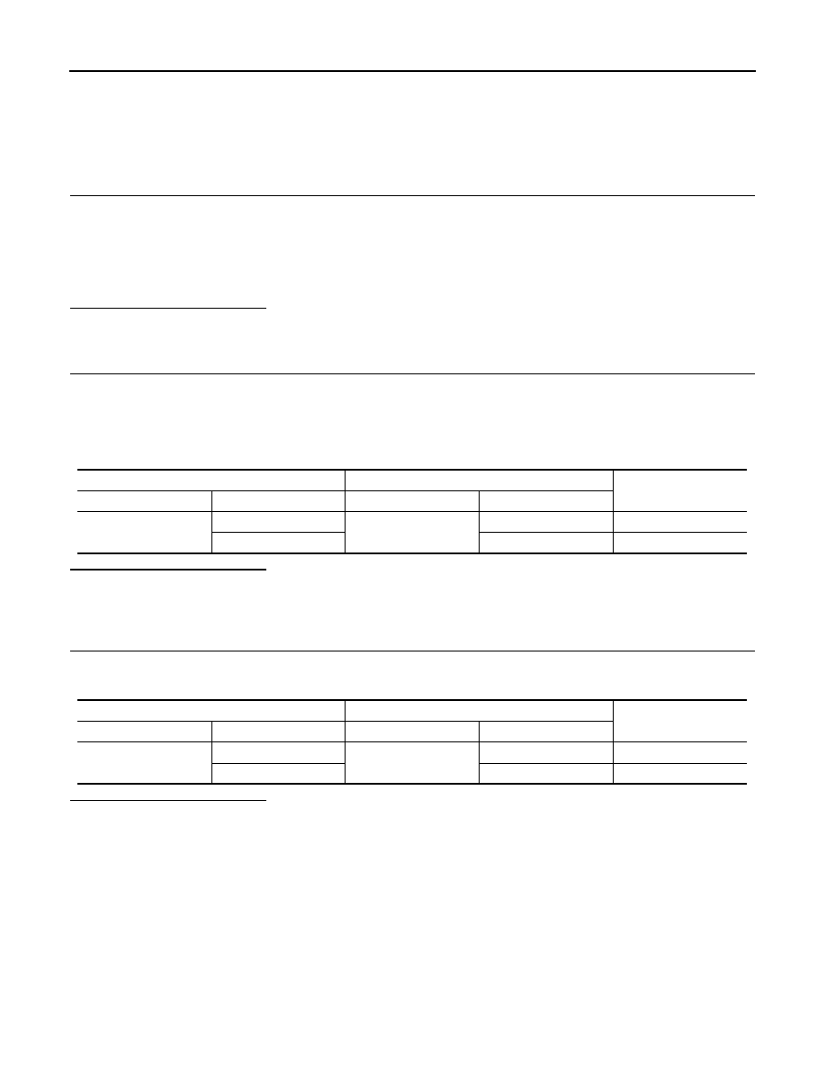
Automatic back door control unit harness connector
Harness connector
Continuity
Connector No.
Terminal No.
Connector No.
Terminal No.
B8
6
B11
57
Existed
7
56
Existed
Harness connector
Combination meter harness connector
Continuity
Connector No.
Terminal No.
Connector No.
Terminal No.
M77
57
M34
21
Existed
56
22
Existed
LAN
MAIN LINE BETWEEN M&A AND DLC CIRCUIT
LAN-217
< DTC/CIRCUIT DIAGNOSIS >
[CAN SYSTEM (TYPE 10)]
C
D
E
F
G
H
I
J
K
L
B
A
O
P
N
MAIN LINE BETWEEN M&A AND DLC CIRCUIT
Diagnosis Procedure
INFOID:0000000010093477
1.
CHECK HARNESS CONTINUITY (OPEN CIRCUIT)
1.
Turn the ignition switch OFF.
2.
Disconnect the battery cable from the negative terminal.
3.
Disconnect the following harness connectors.
-
ECM
-
Combination meter
4.
Check the continuity between the combination meter harness connector and the data link connector.
Is the inspection result normal?
YES (Present error)>>Check CAN system type decision again.
YES (Past error)>>Error was detected in the main line between the combination meter and the data link con-
nector.
NO
>> Repair the main line between the combination meter and the data link connector.
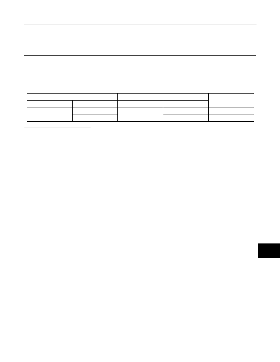
Combination meter harness connector
Data link connector
Continuity
Connector No.
Terminal No.
Connector No.
Terminal No.
M34
21
M4
6
Existed
22
14
Existed
LAN-218
< DTC/CIRCUIT DIAGNOSIS >
[CAN SYSTEM (TYPE 10)]
MAIN LINE BETWEEN DLC AND TCM CIRCUIT
MAIN LINE BETWEEN DLC AND TCM CIRCUIT
Diagnosis Procedure
INFOID:0000000010093478
1.
CHECK CONNECTOR
1.
Turn the ignition switch OFF.
2.
Disconnect the battery cable from the negative terminal.
3.
Check the following terminals and connectors for damage, bend and loose connection (connector side
and harness side).
-
Harness connector M11
-
Harness connector E105
Is the inspection result normal?
YES
>> GO TO 2.
NO
>> Repair the terminal and connector.
2.
CHECK HARNESS CONTINUITY (OPEN CIRCUIT)
1.
Disconnect the harness connectors M11 and E105.
2.
Check the continuity between the data link connector and the harness connector.
Is the inspection result normal?
YES
>> GO TO 3.
NO
>> Repair the main line between the data link connector and the harness connector M11.
3.
CHECK HARNESS CONTINUITY (OPEN CIRCUIT)
1.
Disconnect the harness connectors E6 and F123.
2.
Check the continuity between the harness connectors.
Is the inspection result normal?
YES (Present error)>>Check CAN system type decision again.
YES (Past error)>>Error was detected in the main line between the data link connector and the TCM.
NO
>> Repair the main line between the harness connectors E105 and E6.
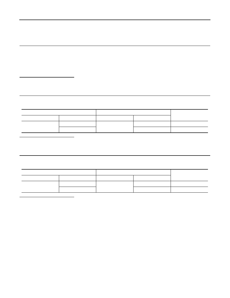
Data link connector
Harness connector
Continuity
Connector No.
Terminal No.
Connector No.
Terminal No.
M4
6
M11
12
Existed
14
11
Existed
Harness connector
Harness connector
Continuity
Connector No.
Terminal No.
Connector No.
Terminal No.
E105
12
E6
1
Existed
11
8
Existed
Нет комментариевНе стесняйтесь поделиться с нами вашим ценным мнением.
Текст