Nissan Murano. Manual — part 74
AV-74
< ECU DIAGNOSIS INFORMATION >
[BASE AUDIO WITH COLOR DISPLAY]
AV CONTROL UNIT
51
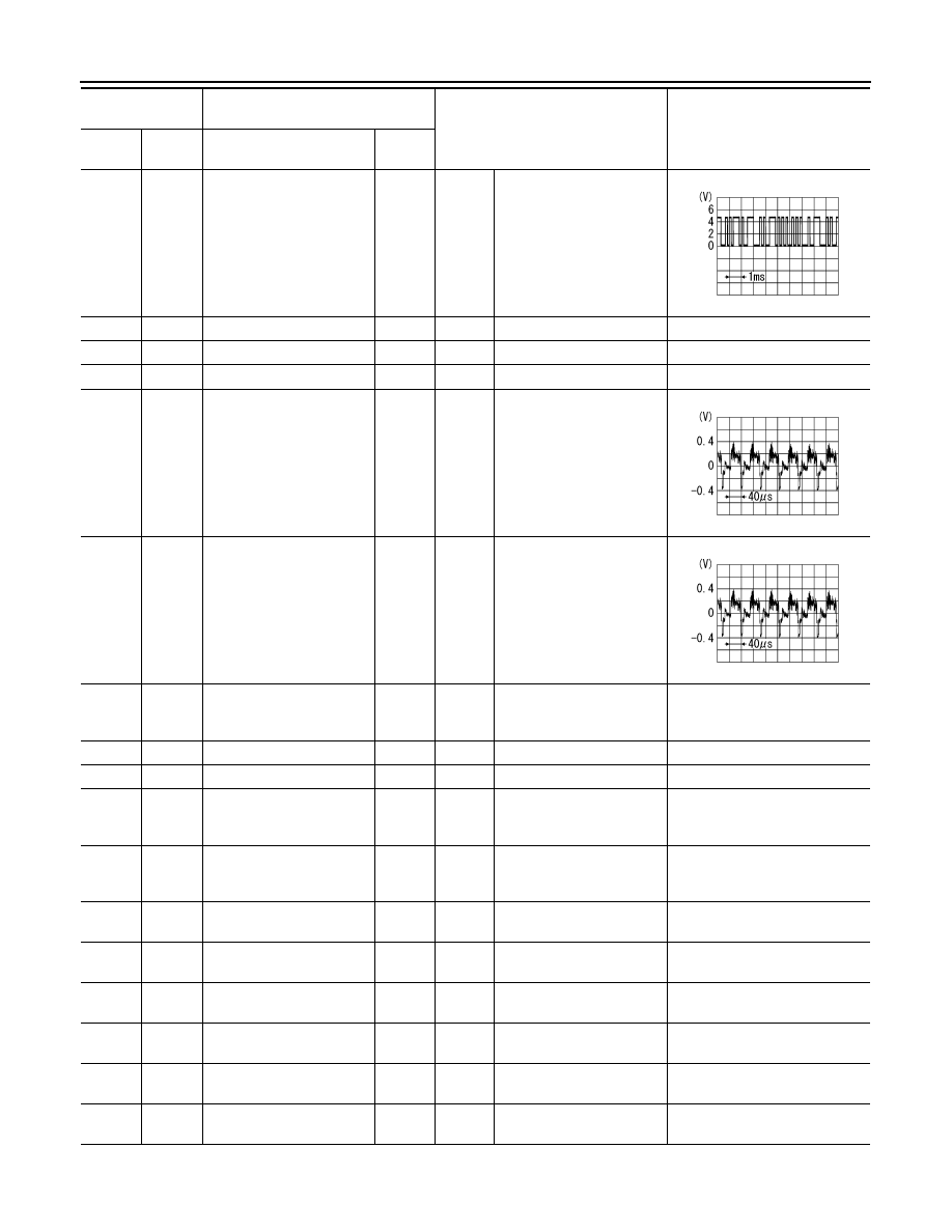
(P)
Ground
Communication signal
(CONT
→
DISP)
Output
Ignition
switch
ON
When adjusting display
brightness.
52
—
Shield
—
—
—
—
57
—
Shield
—
—
—
—
58
—
Shield
—
—
—
—
61
(Y)
Ground
AUX image signal
Input
Ignition
switch
ON
At AUX image is displayed.
62
(R)
Ground
Camera image signal
Input
Ignition
switch
ON
At camera image is dis-
played.
69
(BR)
Ground
AUX image signal ground
—
Ignition
switch
ON
—
0 V
70
—
Shield
—
—
—
—
71
—
Shield
—
—
—
—
72
(LG)
Ground
Camera ground
—
Ignition
switch
ON
—
0 V
73
(V)
Ground
Camera power supply
Output
Ignition
switch
ON
Selector lever is in “R” posi-
tion.
6.0 V
76
(LG)
—
AV communication signal
(L)
Input/
Output
—
—
—
77
(SB)
—
AV communication signal
(H)
Input/
Output
—
—
—
78
(LG)
—
AV communication signal
(L)
Input/
Output
—
—
—
79
(SB)
—
AV communication signal
(H)
Input/
Output
—
—
—
80
(P)
—
CAN–L
Input/
Output
—
—
—
81
(L)
—
CAN–H
Input/
Output
—
—
—
Terminal
(Wire color)
Description
Condition
Reference value
(Approx.)
+
–
Signal name
Input/
Output
PKIB5039J
SKIB2251J
SKIB2251J
AV
AV CONTROL UNIT
AV-75
< ECU DIAGNOSIS INFORMATION >
[BASE AUDIO WITH COLOR DISPLAY]
C
D
E
F
G
H
I
J
K
L
M
B
A
O
P
82
(V)
Ground
Switch ground
—
Ignition
switch
ON
—
0 V
86
—
Shield
—
—
—
—
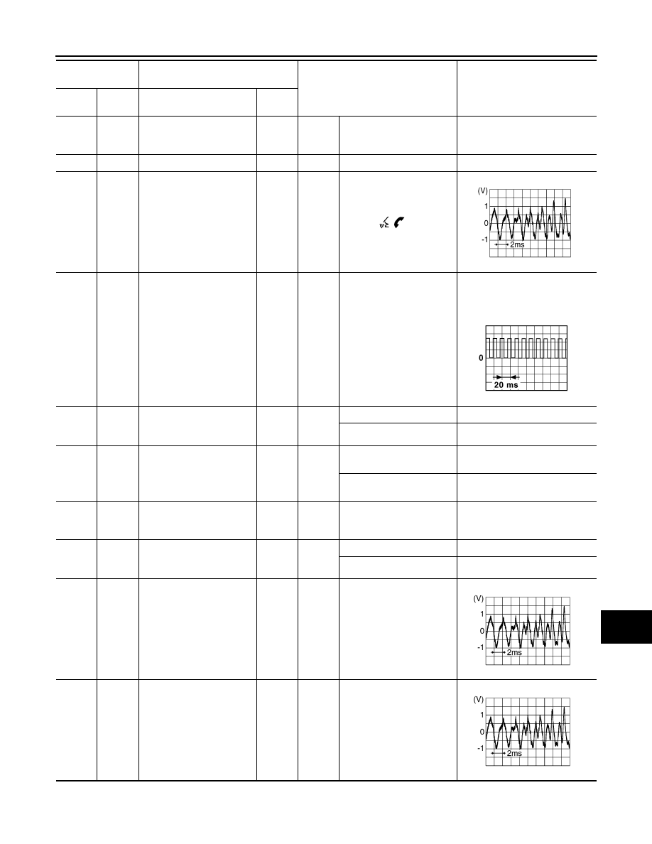
87
(R)
88
(L)
TEL voice signal
Input
Ignition
switch
ON
During voice guide output
with
the
switch
pressed.
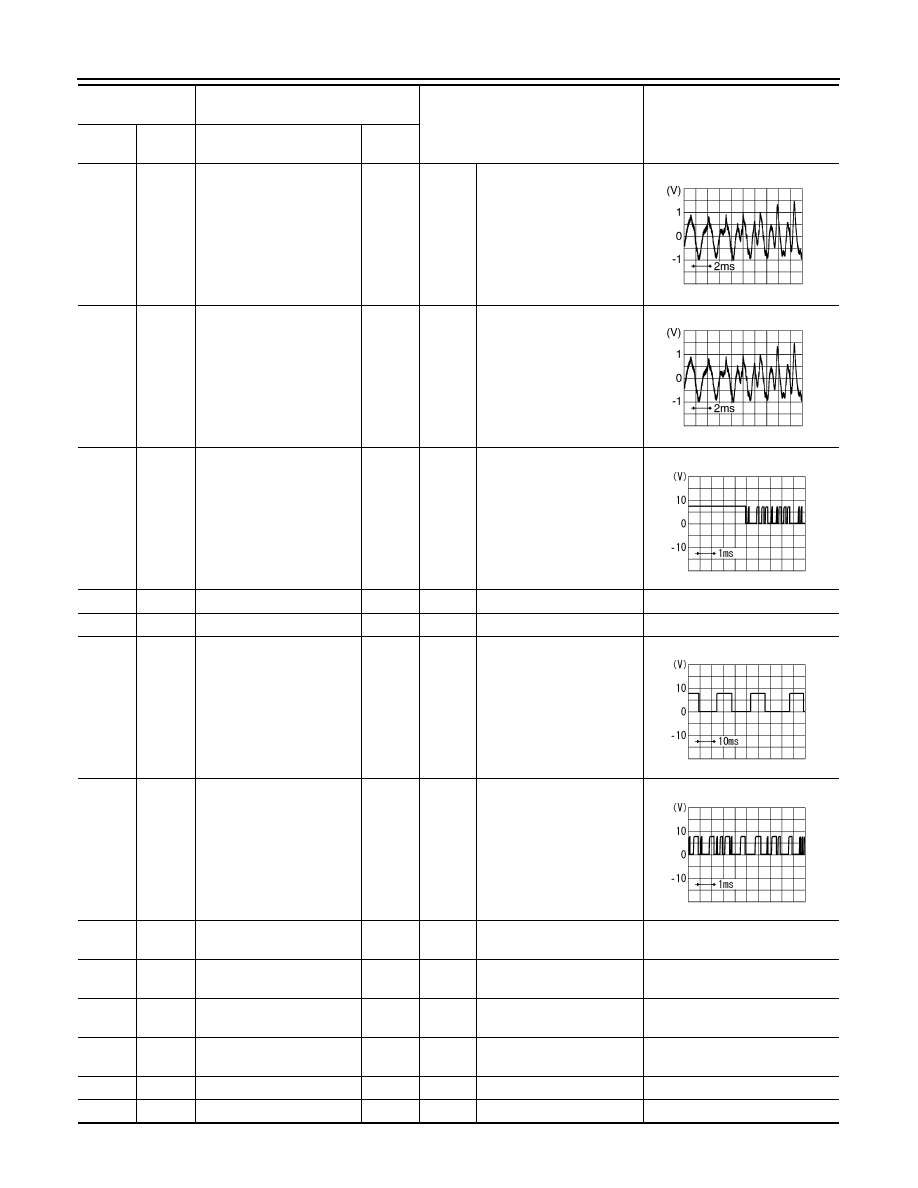
92
(V)
Ground
Vehicle speed signal (8-
pulse)
Input
Ignition
switch
ON
When vehicle speed is ap-
prox. 40 km/h (25 MPH)
NOTE:
The maximum voltage varies de-
pending on the specification
(destination unit).
93
(G)
Ground
Parking brake signal
Input
Ignition
switch
ON
Parking brake is applied.
4.5 V
Parking brake is released.
0 V
94
(SB)
Ground
Reverse signal
Input
Ignition
switch
ON
Selector lever is in R posi-
tion.
12.0 V
Selector lever is in other
than R position.
0 V
95
(G)
Ground
Ignition signal
Input
Ignition
switch
ON
—
Battery voltage
96
(W)
Ground
Disk eject signal
Input
Ignition
switch
ON
Pressing the eject switch.
0 V
Except for above.
5.0 V
103
(B)
102
(W)
AUX sound signal LH
Input
Ignition
switch
ON
When AUX mode is select-
ed.
104
(R)
102
(W)
AUX sound signal RH
Input
Ignition
switch
ON
When AUX mode is select-
ed.
Terminal
(Wire color)
Description
Condition
Reference value
(Approx.)
+
–
Signal name
Input/
Output
SKIB3609E
JSNIA0012GB
SKIB3609E
SKIB3609E
AV-76
< ECU DIAGNOSIS INFORMATION >
[BASE AUDIO WITH COLOR DISPLAY]
AV CONTROL UNIT
120
(G)
124
(B)
Satellite radio sound signal
LH
Input
Ignition
switch
ON
When satellite radio mode
is selected.
121
(W)
125
(R)
Satellite radio sound signal
RH
Input
Ignition
switch
ON
When satellite radio mode
is selected.
122
(B)
Ground
Communication signal
(CONT
→
SAT)
Output
Ignition
switch
ON
When satellite radio mode
is selected.
126
—
Shield
—
—
—
—
127
—
Shield
—
—
—
—
129
(R)
Ground
Request signal
(SAT
→
CONT)
Input
Ignition
switch
ON
When satellite radio mode
is selected.
130
(W)
Ground
Communication signal
(SAT
→
CONT)
Input
Ignition
switch
ON
When satellite radio mode
is selected.
132
(G)
—
USB ground
—
—
—
—
133
(W)
—
USB D
−
signal
—
—
—
—
134
(R)
—
V BUS signal
—
—
—
—
135
(L)
—
USB D+ signal
—
—
—
—
136
—
Shield
—
—
—
—
137
—
FM sub
Input
—
—
—
Terminal
(Wire color)
Description
Condition
Reference value
(Approx.)
+
–
Signal name
Input/
Output
SKIB3609E
SKIB3609E
SKIA9301J
SKIA9299J
SKIA9300J
AV
AV CONTROL UNIT
AV-77
< ECU DIAGNOSIS INFORMATION >
[BASE AUDIO WITH COLOR DISPLAY]
C
D
E
F
G
H
I
J
K
L
M
B
A
O
P
DTC Index
INFOID:0000000009721607
SELF-DIAGNOSIS RESULTS DISPLAY ITEM
138
—
AM - FM main
Input
—
—
—
139
—
Antenna amp. ON signal
Output
Ignition
switch
ON
—
12.0 V
Terminal
(Wire color)
Description
Condition
Reference value
(Approx.)
+
–
Signal name
Input/
Output
DTC
Display item
Refer to
U1000
CAN COMM CIRCUIT [U1000]
U1010
CONTROL UNIT (CAN) [1010]
U1200
Cont Unit [U1200]
U1216
CAN CONT [U1216]
U1232
ST ANGLE SEN CALIB [1232]
U1243
FRONT DISP CONN [U1243]
U1255
SAT CONN [U1255]
U1310
CONTROL UNIT (AV) [U1310]
U1300
U1240
• AV COMM CIRCUIT [U1300]
• SWITCH CONN [U1240]
U1300
U1256
• AV COMM CIRCUIT [U1300]
• HAND FREE CONN [U1256]
U1300
U1240
U1256
• AV COMM CIRCUIT [U1300]
• SWITCH CONN [U1240]
• HAND FREE CONN [U1256]
Нет комментариевНе стесняйтесь поделиться с нами вашим ценным мнением.
Текст