Nissan Murano. Manual — part 791
INSPECTION AND ADJUSTMENT
GI-59
< BASIC INSPECTION >
C
D
E
F
G
H
I
J
K
L
M
B
GI
N
O
P
INSPECTION AND ADJUSTMENT
ADDITIONAL SERVICE WHEN REMOVING BATTERY NEGATIVE TERMINAL
ADDITIONAL SERVICE WHEN REMOVING BATTERY NEGATIVE TERMINAL : Re-
quired Procedure After Battery Disconnection
INFOID:0000000009720552
*: Not equipped.
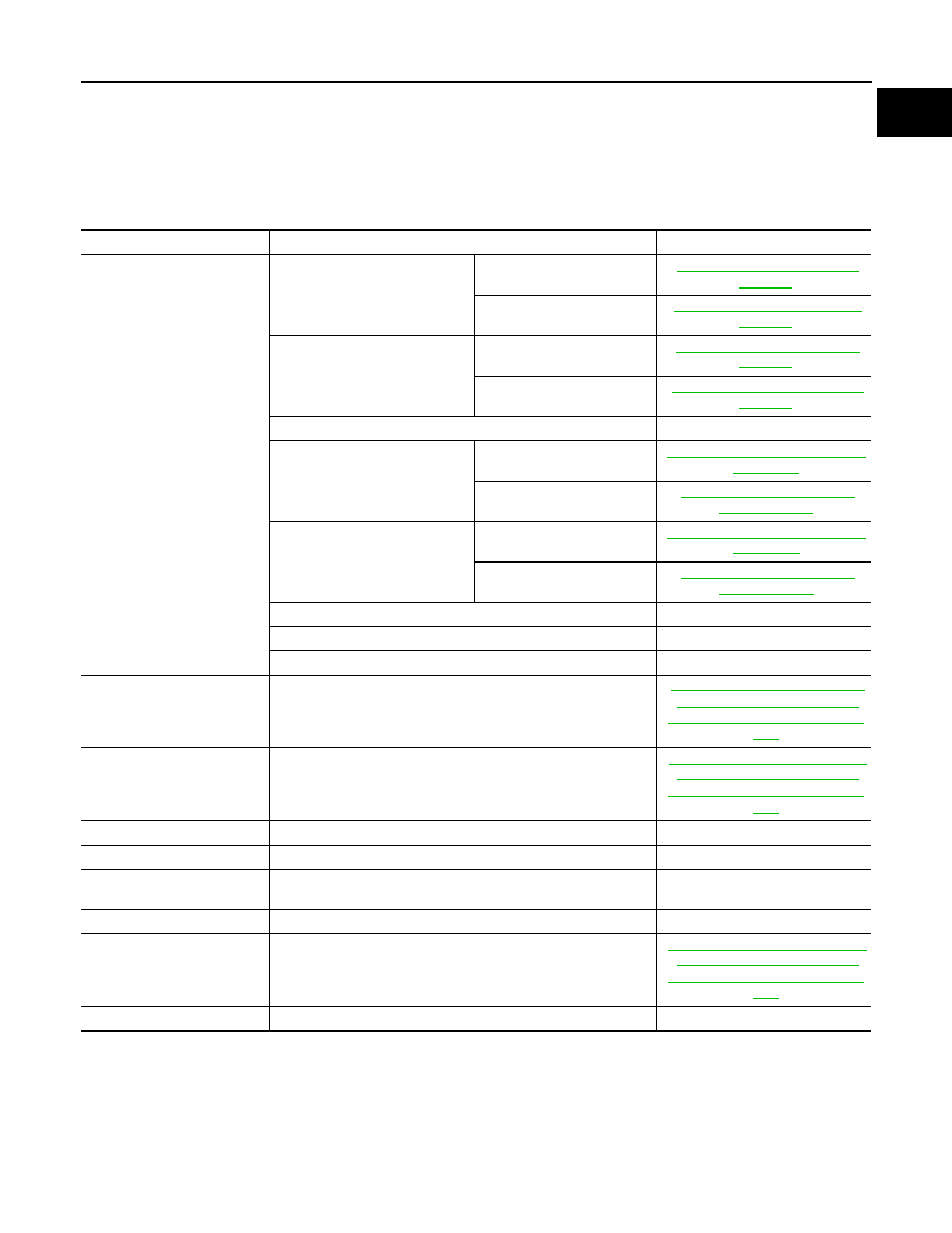
SYSTEM
ITEM
REFERENCE
Automatic air conditioning
system
Temperature setting trimmer
WITHOUT 7 INCH DISPLAY
WITH 7 INCH DISPLAY
Foot position setting trimmer
WITHOUT 7 INCH DISPLAY
HAC-10, "Foot Position Setting
WITH 7 INCH DISPLAY
HAC-136, "Foot Position Setting
Inlet port memory function*
—
Inlet port memory function (FRE)
WITHOUT 7 INCH DISPLAY
HAC-11, "Inlet Port Memory Func-
WITH 7 INCH DISPLAY
Inlet port memory function (REC)
WITHOUT 7 INCH DISPLAY
HAC-11, "Inlet Port Memory Func-
WITH 7 INCH DISPLAY
Gas sensor sensitivity adjustment function*
—
Auto intake switch interlocking movement change*
—
Clean switch interlocking movement change*
—
Automatic drive positioner
Automatic drive positioner system
Power window control
Power window control system
Sunroof system
Sunroof system
—
Sunshade system
Sunshade system
—
Rear view monitor
Rear view monitor predictive course line center position adjust-
ment
—
Around view monitor*
Predictive course line center position adjustment
—
Automatic back door system
Automatic back door system
Engine oil level read*
Engine oil level read
—
HA-1
VENTILATION, HEATER & AIR CONDITIONER
C
D
E
F
G
H
J
K
L
M
SECTION
HA
A
B
HA
N
O
P
CONTENTS
HEATER & AIR CONDITIONING SYSTEM
BASIC INSPECTION . . . . . . . . .
DIAGNOSIS AND REPAIR WORK FLOW . . .
Work Flow . . . . . . . . . . . . . . . .....
SYSTEM DESCRIPTION . . . . . . . ..
REFRIGERATION SYSTEM . . . . . . . ...
System Diagram . . . . . . . . . . . . . ....
System Description . . . . . . . . . . . . ...
Component Parts Location . . . . . . . . . ....
Component Description . . . . . . . . . . .....
SYMPTOM DIAGNOSIS . . . . . . . ...
REFRIGERATION SYSTEM SYMPTOMS . . ..
Trouble Diagnosis For Unusual Pressure . . . .....
Symptom Table . . . . . . . . . . . . . .....
COMPRESSOR SYSTEM SYMPTOMS . . . .
Symptom Table . . . . . . . . . . . . . ...
PRECAUTION . . . . . . . . . . . ..
PRECAUTIONS . . . . . . . . . . . . ..
FOR USA AND CANADA . . . . . . . . . . ..
FOR MEXICO . . . . . . . . . . . . . . .
Precautions for Removing of Battery Terminal . ...
Precaution for Procedure without Cowl Top Cover
Working with HFC-134a (R-134a) . . . . . . ...
General Refrigerant Precaution . . . . . . . ..
Refrigerant Connection . . . . . . . . . . ...
Service Equipment . . . . . . . . . . . . ..
COMPRESSOR . . . . . . . . . . . . ..
General Precautions . . . . . . . . . . . .
LEAK DETECTION DYE . . . . . . . . ...
General Precautions . . . . . . . . . . . .
PREPARATION . . . . . . . . . . ...
PREPARATION . . . . . . . . . . . . .
Special Service Tool . . . . . . . . . . . .
Commercial Service Tool . . . . . . . . . .
Sealant or/and Lubricant . . . . . . . . . . .
PERIODIC MAINTENANCE . . . . . .
LUBRICANT . . . . . . . . . . . . . ..
Maintenance of Lubricant Quantity . . . . . . ..
Lubricant Adjusting Procedure for Components
Replacement Except Compressor . . . . . . ...
Lubricant Adjusting Procedure for Compressor
Replacement . . . . . . . . . . . . . . ...
REFRIGERATION SYSTEM . . . . . . . .
Inspection . . . . . . . . . . . . . . . .
Performance Chart . . . . . . . . . . . . ..
Refrigerant Leakages . . . . . . . . . . . ..
FLUORESCENT LEAK DETECTOR . . . .
Inspection . . . . . . . . . . . . . . . .
ELECTRICAL LEAK DETECTOR . . . . .
Inspection . . . . . . . . . . . . . . . .
REMOVAL AND INSTALLATION . . . ...
REFRIGERATION SYSTEM . . . . . . . .
Exploded View . . . . . . . . . . . . . . .
Inspection After Installation . . . . . . . . . .
COMPRESSOR . . . . . . . . . . . . .
Exploded View . . . . . . . . . . . . . . .
COMPRESSOR . . . . . . . . . . . . . . ..
HA-2
MAGNET CLUTCH . . . . . . . . . . . . ...
MAGNET CLUTCH : Removal and Installation . ..
Inspection . . . . . . . . . . . . . . . ...
LOW-PRESSURE FLEXIBLE HOSE . . . .
Exploded View . . . . . . . . . . . . . ....
Removal and Installation . . . . . . . . . ....
HIGH-PRESSURE FLEXIBLE HOSE . . . .
Exploded View . . . . . . . . . . . . . ....
Removal and Installation . . . . . . . . . ....
LOW-PRESSURE PIPE . . . . . . . . . .
Exploded View . . . . . . . . . . . . . ....
Removal and Installation . . . . . . . . . ....
HIGH-PRESSURE PIPE . . . . . . . . .
Exploded View . . . . . . . . . . . . . ....
Removal and Installation . . . . . . . . . ....
CONDENSER PIPE ASSEMBLY . . . . . ..
Exploded View . . . . . . . . . . . . . ....
Removal and Installation . . . . . . . . . ....
CONDENSER . . . . . . . . . . . . .
Exploded View . . . . . . . . . . . . . ....
Removal and Installation . . . . . . . . . ....
LIQUID TANK . . . . . . . . . . . . .
Exploded View . . . . . . . . . . . . . ....
Removal and Installation . . . . . . . . . . .
REFRIGERANT PRESSURE SENSOR . . .
Exploded View . . . . . . . . . . . . . .
Removal and Installation . . . . . . . . . . .
EVAPORATOR PIPE ASSEMBLY . . . . .
Exploded View . . . . . . . . . . . . . .
Removal and Installation . . . . . . . . . . .
EVAPORATOR . . . . . . . . . . . . ..
Exploded View . . . . . . . . . . . . . .
Removal and Installation . . . . . . . . . . .
EXPANSION VALVE . . . . . . . . . . .
Exploded View . . . . . . . . . . . . . .
Removal and Installation . . . . . . . . . . .
SERVICE DATA AND SPECIFICATIONS
(SDS) . . . . . . . . . . . . . . ..
SERVICE DATA AND SPECIFICATIONS
(SDS) . . . . . . . . . . . . . . . . .
Compressor . . . . . . . . . . . . . . .
Lubricant . . . . . . . . . . . . . . . . .
Refrigerant . . . . . . . . . . . . . . . ..
Engine Idling Speed . . . . . . . . . . . .
DIAGNOSIS AND REPAIR WORK FLOW
HA-3
< BASIC INSPECTION >
C
D
E
F
G
H
J
K
L
M
A
B
HA
N
O
P
BASIC INSPECTION
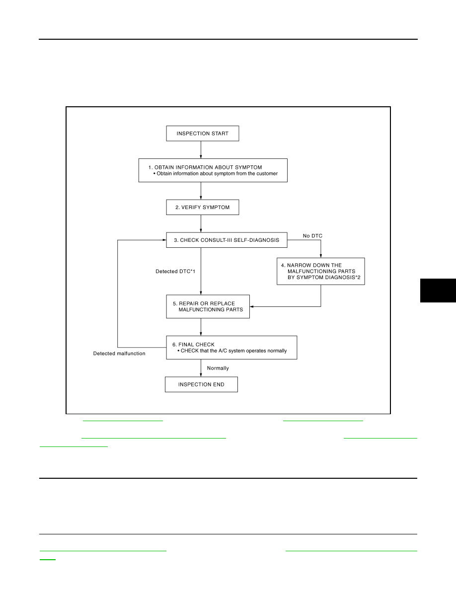
DIAGNOSIS AND REPAIR WORK FLOW
Work Flow
INFOID:0000000009718608
OVERALL SEQUENCE
*1: Refer to
(WITHOUT 7 INCH DISPLAY) or
(WITH 7 INCH
DISPLAY).
*2: Refer to
HAC-108, "Diagnosis Chart By Symptom"
(WITHOUT 7 INCH DISPLAY) or
(WITH 7 INCH DISPLAY).
DETAILED FLOW
1.
OBTAIN INFORMATION ABOUT SYMPTOM
Interview the customer to obtain as much information as possible about the conditions and environment under
which the malfunction occurred.
>> GO TO 2.
2.
VERIFY SYMPTOM
Verify the symptom with operational check based on the information obtained from the customer. Refer to
HAC-134, "Description & Inspection"
(WITHOUT 7 INCH DISPLAY) or
HAC-232, "Diagnosis Chart By Symp-
(WITH 7 INCH DISPLAY).
JSIIA0943GB
Нет комментариевНе стесняйтесь поделиться с нами вашим ценным мнением.
Текст