Nissan Murano. Manual — part 322
DAS-178
< DTC/CIRCUIT DIAGNOSIS >
[BSW]
BLIND SPOT WARNING INDICATOR CIRCUIT
BLIND SPOT WARNING INDICATOR CIRCUIT
Diagnosis Procedure
INFOID:0000000009723385
1.
CHECK BSW INDICATOR CIRCUIT FOR OPEN 1
1.
Turn ignition switch OFF.
2.
Disconnect camera control unit harness connector and BSW indicator harness connector.
3.
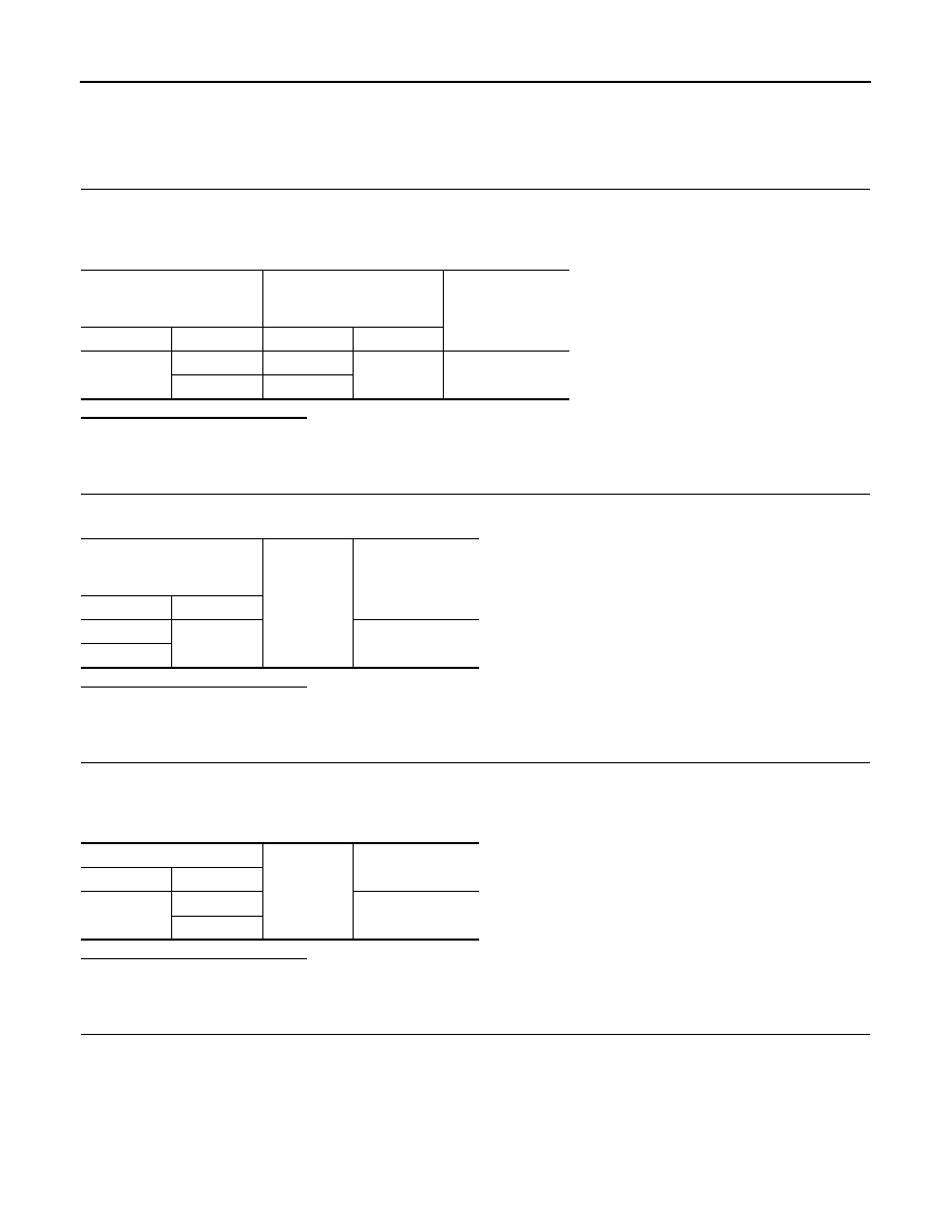
Check continuity between camera control unit harness connector and BSW indicator harness connector.
Is the inspection result normal?
YES
>> GO TO 2.
NO
>> Repair the harnesses or connectors.
2.
CHECK BSW INDICATOR CIRCUIT FOR OPEN 2
Check continuity between BSW indicator harness connector and ground.
Is the inspection result normal?
YES
>> GO TO 3.
NO
>> Repair the harnesses or connectors.
3.
CHECK BSW INDICATOR CIRCUIT FOR SHORT
1.
Turn ignition switch OFF.
2.
Disconnect camera control unit harness connector and BSW indicator harness connector.
3.
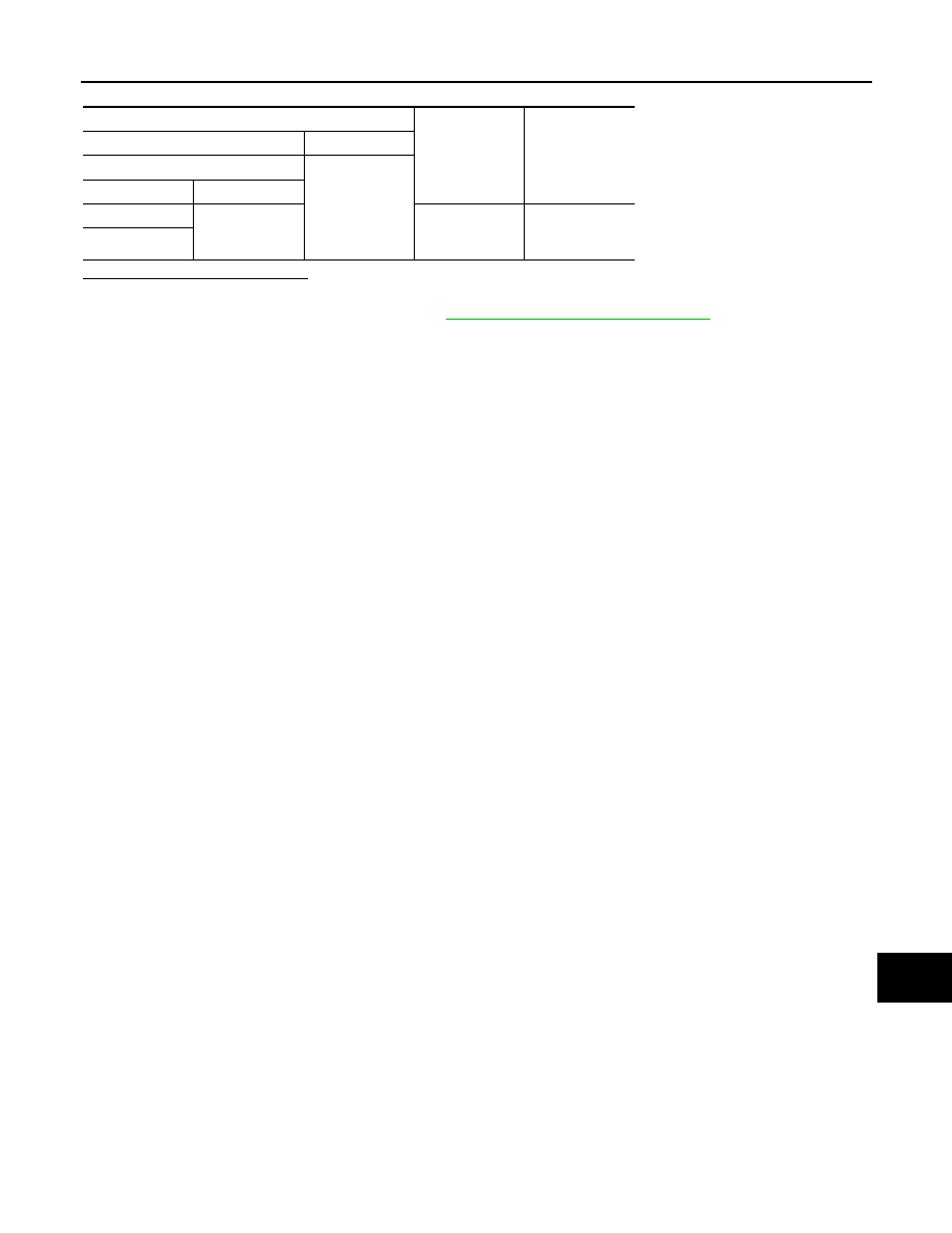
Check continuity between camera control unit harness connector and ground.
Is the inspection result normal?
YES
>> GO TO 4.
NO
>> Repair the harnesses or connectors.
4.
CHECK CAMERA CONTROL UNIT VOLTAGE OUTPUT
1.
Connect camera control unit harness connector.
2.
Check voltage between BSW indicator harness connector and ground.
Camera control unit
BSW indicator
Continuity
Connector
Terminal
Connector
Terminal
B92
7 (LH)
D18 (LH)
1
Existed
8 (RH)
D54 (RH)
BSW indicator
Ground
Continuity
Connector
Terminal
D18 (LH)
2
Existed
D54 (RH)
Camera control unit
Ground
Continuity
Connector
Terminal
B92
7
Not existed
8
DAS
BLIND SPOT WARNING INDICATOR CIRCUIT
DAS-179
< DTC/CIRCUIT DIAGNOSIS >
[BSW]
C
D
E
F
G
H
I
J
K
L
M
B
N
P
A
Is the inspection result normal?
YES
>> Replace BSW indicator.
NO
>> Replace camera control unit. Refer to
DAS-187, "Removal and Installation"
Terminal
Condition
Voltage
(Approx.)
(+)
(
−
)
BSW indicator
Ground
Connector
Terminal
D18 (LH)
1
Ignition switch
OFF
⇒
ON
(Approx. 2 sec.)
6 V
D54 (RH)
DAS-180
< SYMPTOM DIAGNOSIS >
[BSW]
BSW SYSTEM SYMPTOMS
SYMPTOM DIAGNOSIS
BSW SYSTEM SYMPTOMS
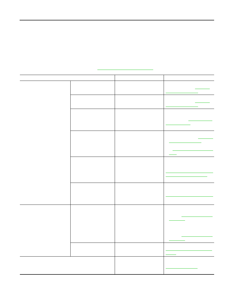
Symptom Table
INFOID:0000000009723386
CAUTION:
Perform the self-diagnosis with CONSULT before the symptom diagnosis. Perform the trouble diagno-
sis if any DTC is detected.
NOTE:
The operational conditions of BSW, refer to
Symptom
Possible cause
Inspection item/Reference page
Indicator/warning lamps do not il-
luminate when ignition switch
OFF
⇒
ON.
BSW warning lamp (Yellow)
does not illuminate
• Combination meter
• Camera control unit
BSW warning lamp does not
turned ON. Refer to
BSW ON indicator lamp
(Green) does not illuminate
• Combination meter
• Camera control unit
BSW ON indicator lamp does not
turned ON. Refer to
Warning systems ON indica-
tor (on the warning systems
switch) does not illuminate
• Harness between camera
control unit and warning sys-
tems switch
• Warning systems switch
• Camera control unit
Warning systems ON indicator
circuit. Refer to
BSW ON indicator lamp
(Green) or BSW warning
lamp (Yellow) do not illumi-
nate
• Combination meter
• Camera control unit
• BSW warning lamp does not
turned ON. Refer to
• BSW ON indicator lamp. Refer
All of indicator/warning
lamps do not illuminate;
• BSW warning lamp
• BSW ON indicator lamp
• Warning systems ON indi-
cator
• Power supply and ground cir-
cuit of camera control unit
• Camera control unit
• Combination meter
Power supply and ground circuit
of camera control unit. Refer to
DAS-165, "CAMERA CONTROL
UNIT : Diagnosis Procedure"
BSW indicator does not turn
ON
• Harness between camera
control unit and BSW indica-
tor
• Camera control unit
• BSW indicator
BSW indicator circuit. Refer to
DAS-178, "Diagnosis Procedure"
BSW system is not activated.
(Indicator/warning lamps illumi-
nate when ignition switch OFF
⇒
ON.)
Warning systems ON indica-
tor is not turned ON
⇔
OFF
when operating warning sys-
tems switch
• Harness between camera
control unit and waning sys-
tems switch
• Harness between warning
systems switch and ground
• Camera control unit
• Warning systems switch
• Warning systems switch cir-
cuit.
Refer to
.
• BSW system setting cannot be
turned ON/OFF on the naviga-
tion screen.
Refer to
Buzzer is not sounding
• Combination meter
• Camera control unit
Meter buzzer circuit. Refer to
WCS-24, "Component Function
Check"
BSW functions are not are not timely
(Example)
• Does not function when approaching a adjacent vehicle while
BSW ON indicator lamp is illuminated
• Rear view camera calibration
• Rear view camera
• Camera control unit
Rear view camera calibration
DAS
BSW SYSTEM SYMPTOMS
DAS-181
< SYMPTOM DIAGNOSIS >
[BSW]
C
D
E
F
G
H
I
J
K
L
M
B
N
P
A
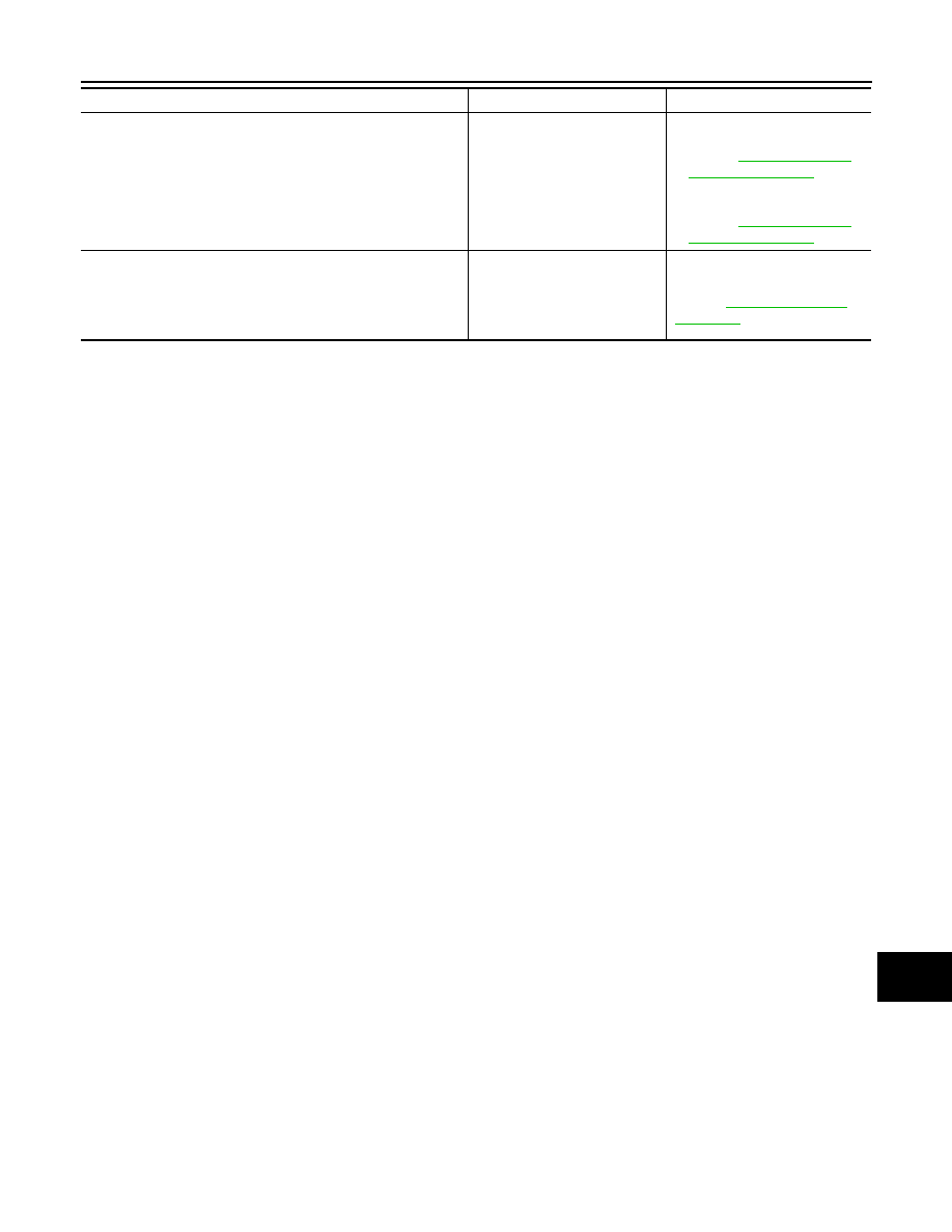
Rear view camera washer is not activated
(Rear window washer is functioning normally)
• Rear view camera washer re-
lay circuit
• Washer switching solenoid
valve circuit
• Pump control unit
• Camera control unit
• Rear view camera washer re-
• Washer switching solenoid
Rear view camera wash is insufficient
• Washer tube (include check
valve)
• Air tube
• Washer/Air nozzle
(Rear view camera)
Rear view camera washer/air
blower function
Refer to
Symptom
Possible cause
Inspection item/Reference page
Нет комментариевНе стесняйтесь поделиться с нами вашим ценным мнением.
Текст