Nissan Murano. Manual — part 1329
ST-10
< SYSTEM DESCRIPTION >
[WITH HEATED STEERING WHEEL]
SYSTEM
SYSTEM
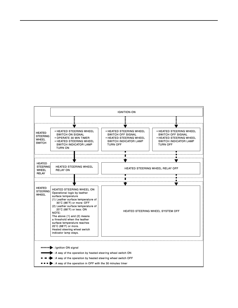
System Description (Heated Steering Wheel)
INFOID:0000000009721461
The heated steering wheel switch controls the heated steering wheel relay. When the heated steering wheel
switch is turned on, the heated steering wheel relay is energized and the heated steering wheel system will
operate. The heated steering wheel system will turn off when the heated steering wheel temperature reaches
approximately 30
°
C (86
°
F). Heated steering wheel system operation can also be canceled by pressing the
heated steering wheel switch again. In addition, the heated steering wheel switch incorporates a timer and
turns OFF the heated steering wheel relay to exit the heated steering wheel system when the operating time
reaches a certain time.
NOTE:
If the surface temperature of the steering wheel is below 20
°
C (68
°
F), the system will heat the steering wheel
and cycle off and on to maintain a temperature above 20
°
C (68
°
F). The indicator lamp will remain on as long
as the system is on. Push the switch again to turn the heated steering wheel system off manually. The indica-
tor lamp will go off.
SYSTEM DIAGRAM
JSGIA0826GB
HEATED STEERING WHEEL
ST-11
< WIRING DIAGRAM >
[WITH HEATED STEERING WHEEL]
C
D
E
F
H
I
J
K
L
M
A
B
ST
N
O
P
WIRING DIAGRAM
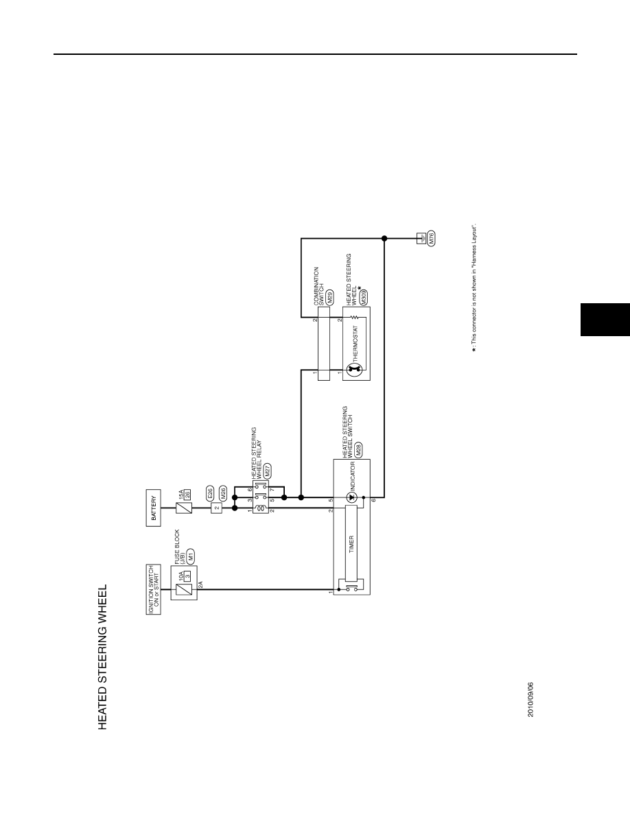
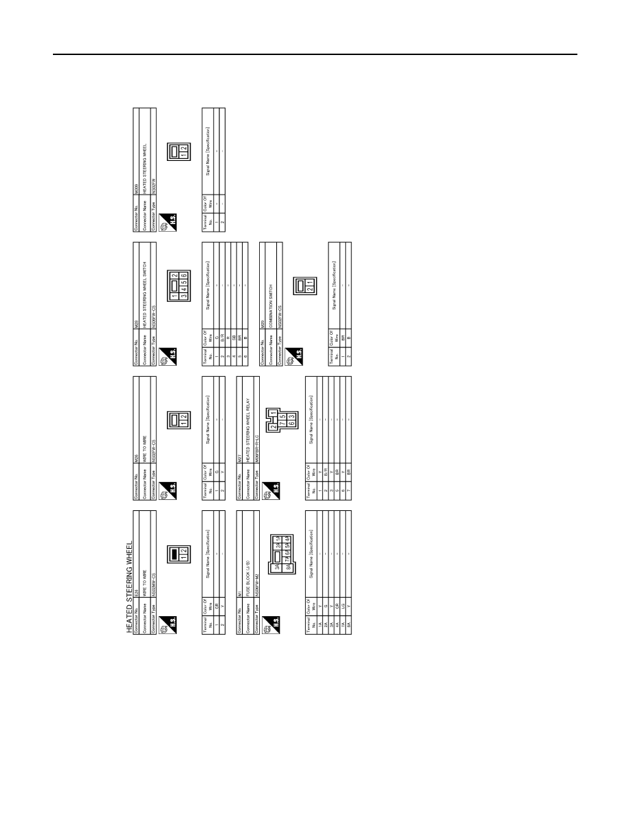
HEATED STEERING WHEEL
Wiring Diagram
INFOID:0000000009721462
JCGWM0468GB
ST-12
< WIRING DIAGRAM >
[WITH HEATED STEERING WHEEL]
HEATED STEERING WHEEL
JRGWC0750GB
DIAGNOSIS AND REPAIR WORK FLOW
ST-13
< BASIC INSPECTION >
[WITH HEATED STEERING WHEEL]
C
D
E
F
H
I
J
K
L
M
A
B
ST
N
O
P
BASIC INSPECTION
DIAGNOSIS AND REPAIR WORK FLOW
WorkFlow (Heated Steering Wheel)
INFOID:0000000009721463
DETAILED FLOW
1.
OBTAIN INFORMATION ABOUT SYMPTOM
Interview the customer to obtain the malfunction information (conditions and environment when the malfunc-
tion occurred) as much as possible when the customer brings the vehicle in.
>> GO TO 2.
2.
REPRODUCE THE MALFUNCTION INFORMATION
Check the malfunction on the vehicle that the customer describes.
Inspect the relation of the symptoms and the condition when the symptoms occur.
>> GO TO 3.
3.
IDENTIFY THE MALFUNCTIONING SYSTEM WITH “SYMPTOM DIAGNOSIS”
Use “Symptom diagnosis” from the symptom inspection result in step 2 and then identify where to start per-
forming the diagnosis based on possible causes and symptoms.
>> GO TO 4.
4.
IDENTIFY THE MALFUNCTIONING PARTS WITH “COMPONENT DIAGNOSIS”
Perform the diagnosis with “Component diagnosis” of the applicable system.
>> GO TO 5.
5.
REPAIR OR REPLACE THE MALFUNCTIONING PARTS
Repair or replace the specified malfunctioning parts.
>> GO TO 6.
6.
FINAL CHECK
Check that malfunctions are not reproduced when obtaining the malfunction information from the customer,
referring to the symptom inspection result in step 2.
Are the malfunctions corrected?
YES
>> INSPECTION END
NO
>> GO TO 2.
Нет комментариевНе стесняйтесь поделиться с нами вашим ценным мнением.
Текст