Nissan Murano. Manual — part 1484
WW-4
< BASIC INSPECTION >
DIAGNOSIS AND REPAIR WORK FLOW
BASIC INSPECTION
DIAGNOSIS AND REPAIR WORK FLOW
Work Flow
INFOID:0000000009719709
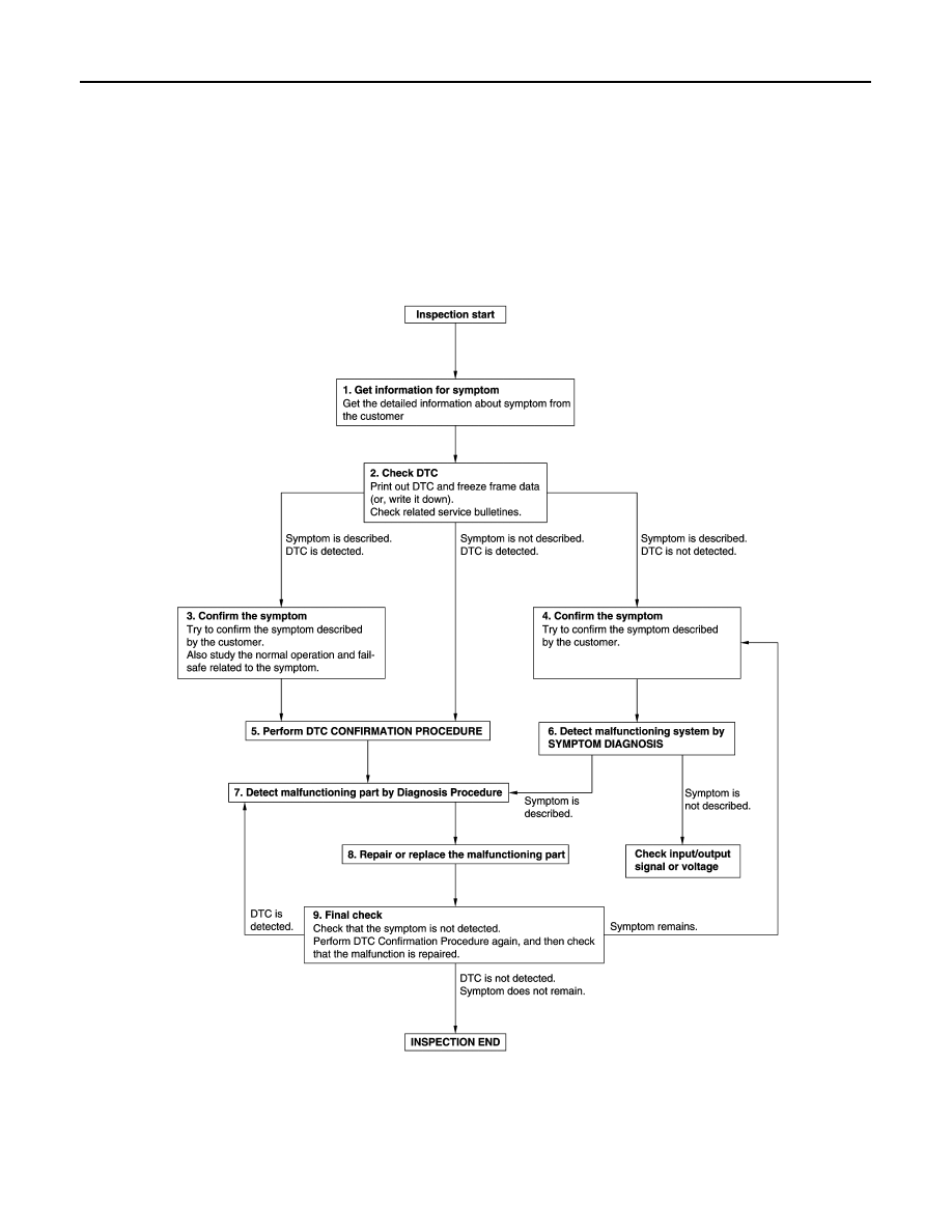
OVERALL SEQUENCE
DETAILED FLOW
JMKIA8652GB

DIAGNOSIS AND REPAIR WORK FLOW
WW-5
< BASIC INSPECTION >
C
D
E
F
G
H
I
J
K
M
A
B
WW
N
O
P
1.
GET INFORMATION FOR SYMPTOM
1.
Get detailed information from the customer about the symptom (the condition and the environment when
the incident/malfunction occurs).
2.
Check operation condition of the function that is malfunctioning.
>> GO TO 2.
2.
CHECK DTC
1.
Check DTC.
2.
Perform the following procedure if DTC is detected.
-
Record DTC and freeze frame data (Print them out using CONSULT.)
-
Erase DTC.
-
Study the relationship between the cause detected by DTC and the symptom described by the customer.
3.
Check related service bulletins for information.
Are any symptoms described and any DTC detected?
Symptom is described, DTC is detected>>GO TO 3.
Symptom is described, DTC is not detected>>GO TO 4.
Symptom is not described, DTC is detected>>GO TO 5.
3.
CONFIRM THE SYMPTOM
Try to confirm the symptom described by the customer.
Also study the normal operation and fail-safe related to the symptom.
Verify relation between the symptom and the condition when the symptom is detected.
>> GO TO 5.
4.
CONFIRM THE SYMPTOM
Try to confirm the symptom described by the customer.
Verify relation between the symptom and the condition when the symptom is detected.
>> GO TO 6.
5.
PERFORM DTC CONFIRMATION PROCEDURE
Perform DTC CONFIRMATION PROCEDURE for the detected DTC, and then check that DTC is detected
again. At this time, always connect CONSULT to the vehicle, and check self diagnostic results in real time.
If two or more DTCs are detected, refer to
BCS-90, "DTC Inspection Priority Chart"
(BCM) or
(IPDM E/R), and determine trouble diagnosis order.
NOTE:
• Freeze frame data is useful if the DTC is not detected.
• Perform Component Function Check if DTC CONFIRMATION PROCEDURE is not included on Service
Manual. This simplified check procedure is an effective alternative though DTC cannot be detected during
this check.
If the result of Component Function Check is NG, it is the same as the detection of DTC by DTC CONFIR-
MATION PROCEDURE.
Is DTC detected?
YES
>> GO TO 7.
NO
>> Check according to
GI-44, "Intermittent Incident"
.
6.
DETECT MALFUNCTIONING SYSTEM BY SYMPTOM DIAGNOSIS
Detect malfunctioning system according to SYMPTOM DIAGNOSIS based on the confirmed symptom in step
4, and determine the trouble diagnosis order based on possible causes and symptom.
Is the symptom described?
YES
>> GO TO 7.
NO
>> Monitor input data from related sensors or check voltage of related module terminals using CON-
SULT.
7.
DETECT MALFUNCTIONING PART BY DIAGNOSIS PROCEDURE
WW-6
< BASIC INSPECTION >
DIAGNOSIS AND REPAIR WORK FLOW
Inspect according to Diagnosis Procedure of the system.
Is malfunctioning part detected?
YES
>> GO TO 8.
NO
>> Check according to
GI-44, "Intermittent Incident"
.
8.
REPAIR OR REPLACE THE MALFUNCTIONING PART
1.
Repair or replace the malfunctioning part.
2.
Reconnect parts or connectors disconnected during Diagnosis Procedure again after repair and replace-
ment.
3.
Check DTC. If DTC is detected, erase it.
>> GO TO 9.
9.
FINAL CHECK
When DTC is detected in step 2, perform DTC CONFIRMATION PROCEDURE again, and then check that the
malfunction is repaired securely.
When symptom is described by the customer, refer to confirmed symptom in step 3 or 4, and check that the
symptom is not detected.
Is DTC detected and does symptom remain?
YES-1 >> DTC is detected: GO TO 7.
YES-2 >> Symptom remains: GO TO 4.
NO
>> Before returning the vehicle to the customer, always erase DTC.
FRONT WIPER AND WASHER SYSTEM
WW-7
< SYSTEM DESCRIPTION >
C
D
E
F
G
H
I
J
K
M
A
B
WW
N
O
P
SYSTEM DESCRIPTION
FRONT WIPER AND WASHER SYSTEM
WITH RAIN SENSOR
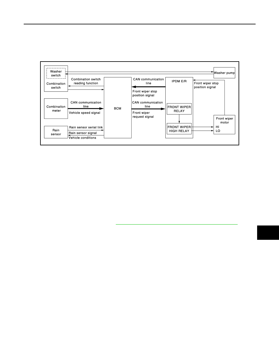
WITH RAIN SENSOR : System Diagram
INFOID:0000000009719710
WITH RAIN SENSOR : System Description
INFOID:0000000009719711
OUTLINE
The front wiper is controlled by each function of BCM and IPDM E/R.
Control by BCM
• Combination switch reading function
• Front wiper control function
Control by IPDM E/R
• Front wiper control function
• Relay control function
Combination meter indicates low washer fluid warning judged with the signal from the washer level switch. For
details of low washer fluid warning, refer to
MWI-26, "INFORMATION DISPLAY : System Description"
.
FRONT WIPER BASIC OPERATION
• BCM detects the combination switch condition by the combination switch reading function.
• BCM transmits the front wiper request signal to IPDM E/R with CAN communication depending on each
operating condition of the front wiper.
• IPDM E/R turns ON/OFF the integrated front wiper relay and the front wiper high relay according to the front
wiper request signal. IPDM E/R provides the power supply to operate the front wiper HI/LO operation.
FRONT WIPER LO OPERATION
• BCM transmits the front wiper request signal (LO) to IPDM E/R with CAN communication according to the
front wiper LO operating condition.
Front wiper LO operating condition
- Ignition switch ON
- Front wiper switch LO or front wiper switch MIST (while pressing)
• IPDM E/R turns ON the integrated front wiper relay according to the front wiper request signal (LO).
FRONT WIPER HI OPERATION
• BCM transmits the front wiper request signal (HI) to IPDM E/R with CAN communication according to the
front wiper HI operating condition.
Front wiper HI operating condition
- Ignition switch ON
- Front wiper switch HI
JPLIA1630GB
Нет комментариевНе стесняйтесь поделиться с нами вашим ценным мнением.
Текст