Nissan Murano. Manual — part 758
FRONT DRIVE SHAFT
FAX-27
< REMOVAL AND INSTALLATION >
[2WD]
C
E
F
G
H
I
J
K
L
M
A
B
FAX
N
O
P
e.
Install dust shields.
CAUTION:
Never reuse dust shields.
4.
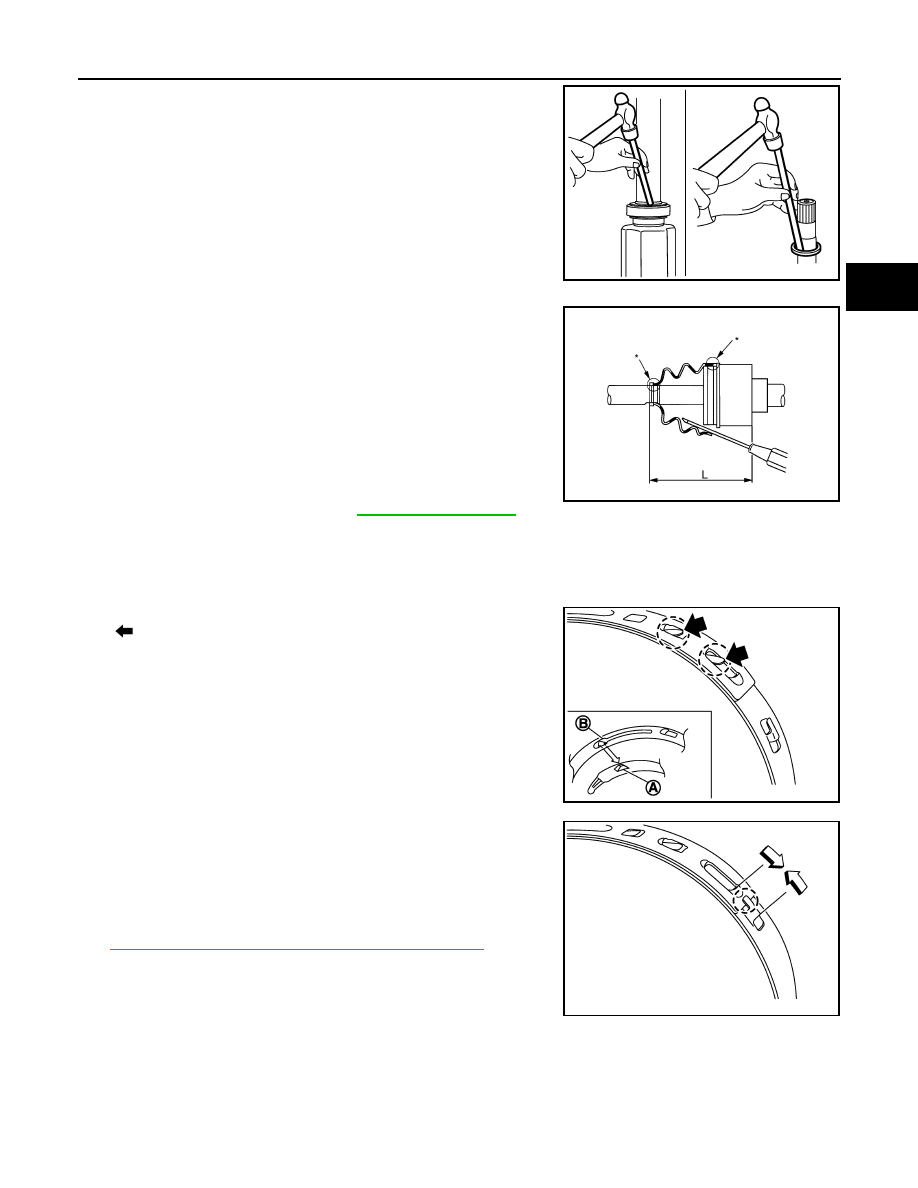
Clean old grease on housing assembly with paper waste.
5.
Install boot securely into grooves (indicated by “*” marks) shown
in the figure.
CAUTION:
If grease adheres to the boot mounting surface (indicated
by “*” mark) on housing assembly, boot may be removed.
Remove all grease from the boot mounting surface.
6.
To prevent from deformation of the boot, adjust the boot installa-
tion length (L) to the specified value shown below by inserting
the suitable tool into the inside of boot from the large diameter
side of boot and discharging inside air.
CAUTION:
• If the boot installation length exceeds the standard, it may cause breakage of boot.
• Be careful not to touch the inside of the boot with the tip of tool.
7.
Install boot bands securely as shown in the figure.
a.
Put boot band in the groove on drive shaft boot. Then fit pawls
(
) into holes to temporary installation.
NOTE:
For the large diameter side, fit projection (A) and guide slit (B) at
first.
b.
Pinch projection on the band with suitable pliers to tighten band.
c.
Insert tip of band below end of the pawl.
8.
Secure housing assembly, and then make sure that they are in
the correct position when rotating boot. Reinstall them with boot
bands when the mounting positions become incorrect.
9.
Assemble boot (wheel side) and joint sub-assembly. Refer to
FAX-22, "WHEEL SIDE : Disassembly and Assembly"
.
10. Install dynamic damper, follow the procedure described below.
a.
Install dynamic damper to shaft.
JPDIF0127ZZ
L
: Refer to
JPDIF0144ZZ
JPDIF0157ZZ
JPDIF0158ZZ
FAX-28
< REMOVAL AND INSTALLATION >
[2WD]
FRONT DRIVE SHAFT
b.
Secure dynamic damper with bands in the following specified
position (A) when installing.
CAUTION:
Never reuse bands.
Inspection
INFOID:0000000009717906
INSPECTION AFTER REMOVAL
• Move joint up/down, left/right, and in the axial directions. Check for motion that is not smooth and for signifi-
cant looseness.
• Check boot for cracks, damage, and leakage of grease.
• Disassemble drive shaft and exchange malfunctioning part if there
is a non-standard condition.
INSPECTION AFTER DISASSEMBLY
Shaft
Check shaft for runout, cracks, or other damage. Replace if necessary.
Dynamic Damper
Check damper for cracks or wear. Replace if necessary.
Joint Sub-Assembly (Wheel Side)
Check the following:
• Joint sub-assembly for rough rotation and excessive axial looseness.
• The inside of the joint sub-assembly for entry of foreign material.
• Joint sub-assembly for compression scars, cracks, and fractures inside of joint sub-assembly.
Replace joint sub-assembly if there are any non-standard conditions of components.
Housing Assembly (Transaxle Side)
Replace housing assembly if there is scratching or wear of housing assembly roller contact surface.
Support Bearing (Right Side)
Make sure wheel bearing rolls freely and is free from noise, cracks, pitting or wear. Replace support bearing if
there are any non-standard conditions.
Support Bearing Bracket (Right Side)
Check for bending, cracks, or damage. Replace support bearing bracket if there are any non-standard condi-
tions.
A
: Refer to
JPDIF0178ZZ
SDIA1190J
SERVICE DATA AND SPECIFICATIONS (SDS)
FAX-29
< SERVICE DATA AND SPECIFICATIONS (SDS)
[2WD]
C
E
F
G
H
I
J
K
L
M
A
B
FAX
N
O
P
SERVICE DATA AND SPECIFICATIONS (SDS)
SERVICE DATA AND SPECIFICATIONS (SDS)
Wheel Bearing
INFOID:0000000009717907
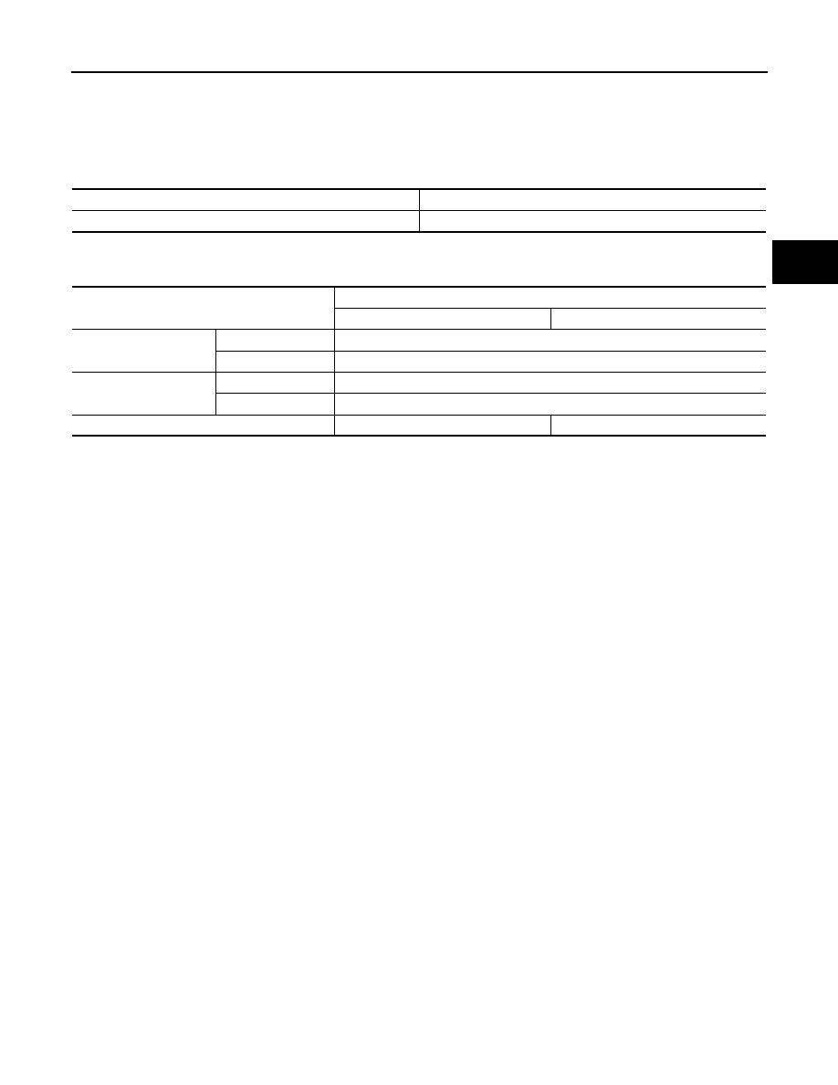
Drive Shaft
INFOID:0000000009717908
Item
Standard
Axial end play
0.05 mm (0.002 in) or less
Item
Standard
Left side
Right side
Grease quantity
Wheel side
170 – 190 g (6.00 – 6.70 oz)
Transaxle side
155 – 175 g (5.47 – 6.17 oz)
Boots installed length
Wheel side
158.6 mm (6.24 in)
Transaxle side
163.67 mm (6.44 in)
Dimension of dynamic damper
—
202 – 208 mm (7.95 – 8.19 in)
FAX-30
< SYMPTOM DIAGNOSIS >
[AWD]
NOISE, VIBRATION AND HARSHNESS (NVH) TROUBLESHOOTING
SYMPTOM DIAGNOSIS
NOISE, VIBRATION AND HARSHNESS (NVH) TROUBLESHOOTING
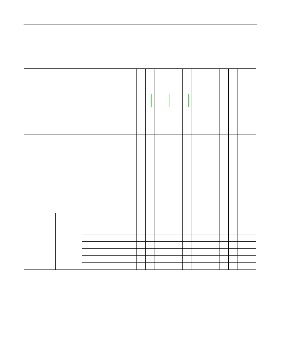
NVH Troubleshooting Chart
INFOID:0000000009717909
Use chart below to find the cause of the symptom. If necessary, repair or replace these parts.
×
: Applicable
Reference
—
—
—
NV
H in
F
A
X
an
d
FSU s
e
c
tio
ns
Re
fe
r to
FRONT AXL
E i
n
t
h
is cha
rt
NVH in WT
section
NVH in WT
section
Ref
e
r t
o
DRIVE
SHAFT
in this
chart
NVH in BR
section
NVH in S
T
section
Possible cause and SUSPECTED PARTS
Ex
ce
ss
iv
e joi
nt an
gl
e
Jo
in
t sl
id
in
g
re
si
st
a
n
c
e
Im
ba
la
nc
e
Imp
rop
er i
ns
ta
lla
ti
o
n,
lo
os
en
es
s
Part
s interf
erence
Whe
e
l be
ari
n
g
da
ma
ge
FRONT A
X
LE
AND FRONT SUSP
ENSION
FRONT A
XLE
TI
RE
ROAD WHEE
L
DRIVE SHAFT
BRAKE
STE
E
RING
Symptom
DRIVE
SHAFT
Noise
×
×
×
×
×
×
×
×
×
Shake
×
×
×
×
×
×
×
×
×
FRONT
AXLE
Noise
×
×
×
×
×
×
×
×
×
Shake
×
×
×
×
×
×
×
×
×
Vibration
×
×
×
×
×
×
×
Shimmy
×
×
×
×
×
×
×
Judder
×
×
×
×
×
×
Poor quality ride or handling
×
×
×
×
×
Нет комментариевНе стесняйтесь поделиться с нами вашим ценным мнением.
Текст