Nissan Murano. Manual — part 572
EC-398
< DTC/CIRCUIT DIAGNOSIS >
[VQ35DE]
P1801 VIAS CONTROL SOLENOID VALVE 2
3.
Check the continuity between VIAS control solenoid valve 2 harness connector and ECM harness con-
nector.
4.
Also check harness for short to ground and short to power.
Is the inspection result normal?
YES
>> GO TO 3.
NO
>> Repair open circuit, short to ground or short to power in harness or connectors.
3.
CHECK VIAS CONTROL SOLENOID VALVE 2
EC-398, "Component Inspection"
Is the inspection result normal?
YES
>> GO TO 4.
NO
>> Replace VIAS control solenoid valve 2. Refer to
.
4.
CHECK INTERMITTENT INCIDENT
GI-44, "Intermittent Incident"
>> INSPECTION END
Component Inspection
INFOID:0000000009720147
1.
CHECK VIAS CONTROL SOLENOID VALVE 2
With CONSULT
1.
Turn ignition switch OFF.
2.
Reconnect all harness connectors disconnected.
3.
Disconnect vacuum hoses connected to VIAS control solenoid valve 2.
4.
Turn ignition switch ON.
5.
Select “VIAS S/V-2” in “ACTIVE TEST” mode with CONSULT.
6.
Check air passage continuity and operation delay time under the
following conditions.
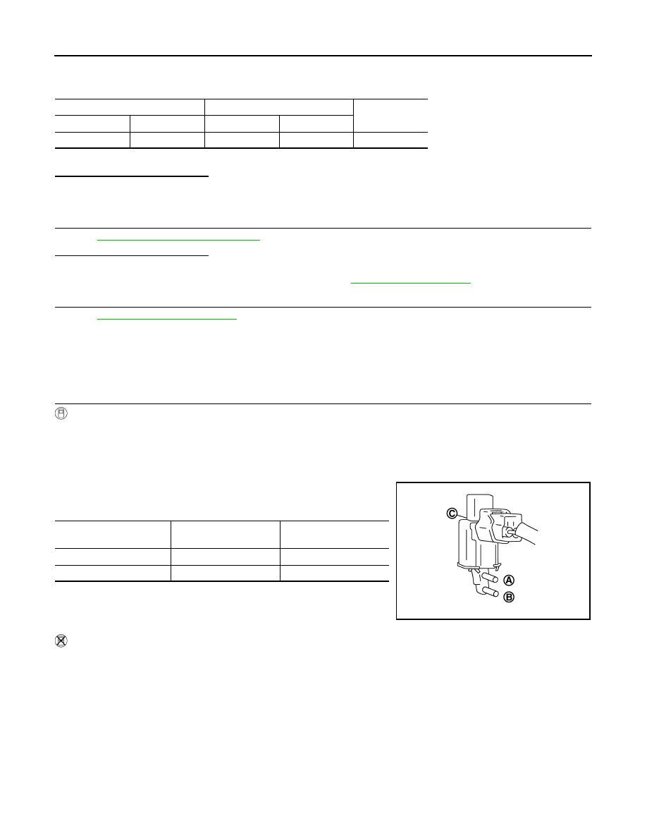
Without CONSULT
1.
Turn ignition switch OFF.
2.
Disconnect VIAS control solenoid valve 2 harness connector.
3.
Disconnect vacuum hoses connected to VIAS volume control solenoid valve 2.
VIAS control solenoid valve 2
ECM
Continuity
Connector
Terminal
Connector
Terminal
F75
2
F7
26
Existed
Condition
(VIAS S/V-2)
Air passage continuity
between (A) and (B)
Air passage continuity
between (A) and (C)
ON
Existed
Not existed
OFF
Not existed
Existed
JMBIA0180ZZ
P1801 VIAS CONTROL SOLENOID VALVE 2
EC-399
< DTC/CIRCUIT DIAGNOSIS >
[VQ35DE]
C
D
E
F
G
H
I
J
K
L
M
A
EC
N
P
O
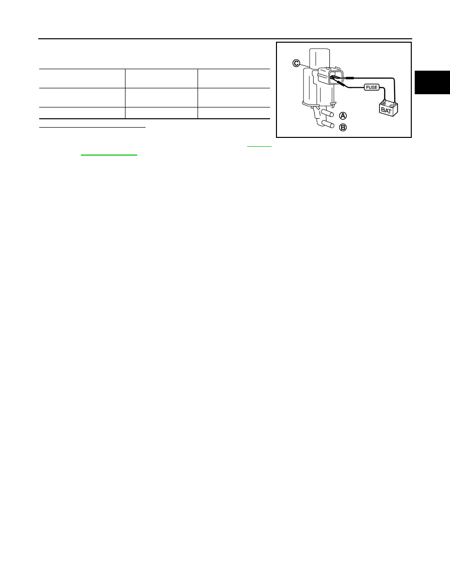
4.
Check air passage continuity and operation delay time under the
following conditions.
Is the inspection result normal?
YES
>> INSPECTION END
NO
>> Replace VIAS control solenoid valve 2. Refer to
Condition
Air passage continuity
between (A) and (B)
Air passage continuity
between (A) and (C)
12 V direct current supply be-
tween terminals 1 and 2
Existed
Not existed
No supply
Not existed
Existed
PBIB2532E
EC-400
< DTC/CIRCUIT DIAGNOSIS >
[VQ35DE]
P1805 BRAKE SWITCH
P1805 BRAKE SWITCH
Description
INFOID:0000000009720148
Brake switch signal is applied to the ECM through the stop lamp switch when the brake pedal is depressed.
This signal is used mainly to decrease the engine speed when the vehicle is being driven.
DTC Logic
INFOID:0000000009720149
DTC DETECTION LOGIC
DTC CONFIRMATION PROCEDURE
1.
PERFORM DTC CONFIRMATION PROCEDURE
1.
Turn ignition switch ON.
2.
Fully depress the brake pedal for at least 5 seconds.
3.
Erase the DTC.
4.
Check 1st trip DTC.
Is 1st trip DTC detected?
YES
>> Go to
NO
>> INSPECTION END
Diagnosis Procedure
INFOID:0000000009720150
1.
CHECK STOP LAMP SWITCH CIRCUIT
1.
Turn ignition switch OFF.
2.
Check the stop lamp when depressing and releasing the brake pedal.
Is the inspection result normal?
YES
>> GO TO 4.
NO
>> GO TO 2.
2.
CHECK STOP LAMP SWITCH POWER SUPPLY CIRCUIT
1.
Disconnect stop lamp switch harness connector.
2.
Check the voltage between stop lamp switch harness connector and ground.
Is the inspection result normal?
YES
>> GO TO 4.
NO
>> GO TO 3.
3.
DETECT MALFUNCTIONING PART
Check the following.
• Fuse block (J/B) connector E103
• 10 A fuse (No. 7)
DTC No.
Trouble diagnosis name
DTC detecting condition
Possible cause
P1805
Brake switch
A brake switch signal is not sent to ECM for ex-
tremely long time while the vehicle is being driv-
en.
• Harness or connectors
(Stop lamp switch circuit is open or short-
ed.)
• Stop lamp switch
Brake pedal
Stop lamp
Fully released
Not illuminated
Slightly depressed
Illuminated
Stop lamp switch
Ground
Voltage
Connector
Terminal
E116
1
Ground
Battery voltage
P1805 BRAKE SWITCH
EC-401
< DTC/CIRCUIT DIAGNOSIS >
[VQ35DE]
C
D
E
F
G
H
I
J
K
L
M
A
EC
N
P
O
• Harness for open or short between battery and stop lamp switch
>> Repair open circuit, short to ground or short to power in harness or connectors.
4.
CHECK STOP LAMP SWITCH INPUT SIGNAL CIRCUIT FOR OPEN AND SHORT
1.
Disconnect stop lamp switch harness connector.
2.
Disconnect ECM harness connector.
3.
Check the continuity between stop lamp switch harness connector and ECM harness connector.
4.
Also check harness for short to ground and short to power.
Is the inspection result normal?
YES
>> GO TO 6.
NO
>> GO TO 5.
5.
DETECT MALFUNCTIONING PART
Check the following.
• Fuse block (J/B) connector E103
• Harness for open or short between ECM and stop lamp switch
>> Repair open circuit, short to ground or short to power in harness or connectors.
6.
CHECK STOP LAMP SWITCH
EC-401, "Component Inspection (Stop Lamp Switch)"
.
Is the inspection result normal?
YES
>> GO TO 7.
NO
>> Replace stop lamp switch. Refer to
.
7.
CHECK INTERMITTENT INCIDENT
GI-44, "Intermittent Incident"
.
>> INSPECTION END
Component Inspection (Stop Lamp Switch)
INFOID:0000000009720151
1.
CHECK STOP LAMP SWITCH-I
1.
Turn ignition switch OFF.
2.
Disconnect stop lamp switch harness connector.
3.
Check harness continuity between stop lamp switch terminals under the following conditions.
Is the inspection result normal?
YES
>> INSPECTION END
NO
>> GO TO 2.
2.
CHECK STOP LAMP SWITCH-II
1.
Adjust stop lamp switch installation. Refer to
BR-9, "Inspection and Adjustment"
2.
Check harness continuity between stop lamp switch terminals under the following conditions.
Stop lamp switch
ECM
Continuity
Connector
Terminal
Connector
Terminal
E116
2
E16
106
Existed
Terminals
Condition
Continuity
1 and 2
Brake pedal
Fully released
Not existed
Slightly depressed
Existed
Нет комментариевНе стесняйтесь поделиться с нами вашим ценным мнением.
Текст