Nissan Murano. Manual — part 698

EXL-204
< SYSTEM DESCRIPTION >
[HALOGEN TYPE]
FRONT FOG LAMP SYSTEM
Component Parts Location
INFOID:0000000009723003
Component Description
INFOID:0000000009723004
1.
Front fog lamp
2.
Combination switch
3.
IPDM E/R
4.
BCM
A.
Engine room (LH)
B.
Behind the combination meter
JPLIA0843ZZ
Part
Description
BCM
• Detects each switch condition by the combination switch reading function.
• Judges the front fog lamp ON/OFF status according to the vehicle condition.
- Requests the front fog lamp relay ON to IPDM E/R (with CAN communication).
IPDM E/R
Controls the integrated relay and supplies voltage to the load according to the request
from BCM (with CAN communication).
Combination switch
(Lighting & turn signal switch)
TURN SIGNAL AND HAZARD WARNING LAMP SYSTEM
EXL-205
< SYSTEM DESCRIPTION >
[HALOGEN TYPE]
C
D
E
F
G
H
I
J
K
M
A
B
EXL
N
O
P
TURN SIGNAL AND HAZARD WARNING LAMP SYSTEM
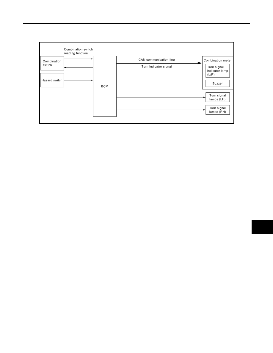
System Diagram
INFOID:0000000009723005
System Description
INFOID:0000000009723006
OUTLINE
Turn signal lamp and the hazard warning lamp is controlled by combination switch reading function and the
flasher control function of BCM.
TURN SIGNAL LAMP OPERATION
• BCM detects the combination switch condition by the combination switch reading function.
• BCM supplies voltage to the right (left) turn signal lamp circuit when the ignition switch is turned ON and the
turn signal switch is in the right (left) position. BCM blinks the turn signal lamp.
HAZARD WARNING LAMP OPERATION
BCM supplies voltage to both turn signal lamp circuit when the hazard switch is turned ON. BCM blinks the
hazard warning lamp.
TURN SIGNAL INDICATOR LAMP AND TURN SIGNAL SOUND OPERATION
• BCM transmits the turn indicator signal to the combination meter with CAN communication while the turn sig-
nal lamp and the hazard warning lamp are operating.
• Combination meter outputs the turn signal sound with the integrated buzzer while blinking the turn signal
indicator lamp according to the turn indicator signal.
HIGH FLASHER OPERATION
• BCM detects the turn signal lamp circuit status by the terminal current value.
• BCM increases the turn signal lamp blinking speed if the bulb or harness open is detected with the turn sig-
nal lamp operating.
NOTE:
The blinking speed is normal while operating the hazard warning lamp.
JPLIA0180GB
EXL-206
< SYSTEM DESCRIPTION >
[HALOGEN TYPE]
TURN SIGNAL AND HAZARD WARNING LAMP SYSTEM
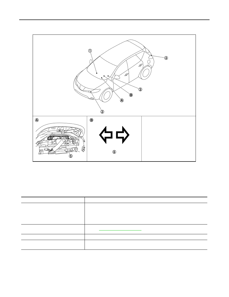
Component Parts Location
INFOID:0000000009723007
Component Description
INFOID:0000000009723008
1.
Hazard switch
2.
Front turn signal lamp
3.
Combination switch
4.
Rear turn signal lamp
5.
BCM
6.
Turn signal indicator lamp
A.
Behind the combination meter
B.
On the combination meter
JPLIA0844ZZ
Part
Description
BCM
• Detects each switch condition by the combination switch reading function.
• Judges the blinks of the turn signal lamp and the hazard warning lamp from each
switch status. The applicable turn signal lamp blinks.
- Requests the turn signal indicator lamp blink to the combination meter (with CAN
communication).
Combination switch
(Lighting & turn signal switch)
Hazard switch
Inputs the hazard switch ON/OFF signal to BCM.
Combination meter
(Turn signal indicator lamp & buzzer)
Blinks the turn signal indicator lamp and outputs the turn signal operating sound with
integrated buzzer according to the request from BCM (with CAN communication).
PARKING, LICENSE PLATE AND TAIL LAMPS SYSTEM
EXL-207
< SYSTEM DESCRIPTION >
[HALOGEN TYPE]
C
D
E
F
G
H
I
J
K
M
A
B
EXL
N
O
P
PARKING, LICENSE PLATE AND TAIL LAMPS SYSTEM
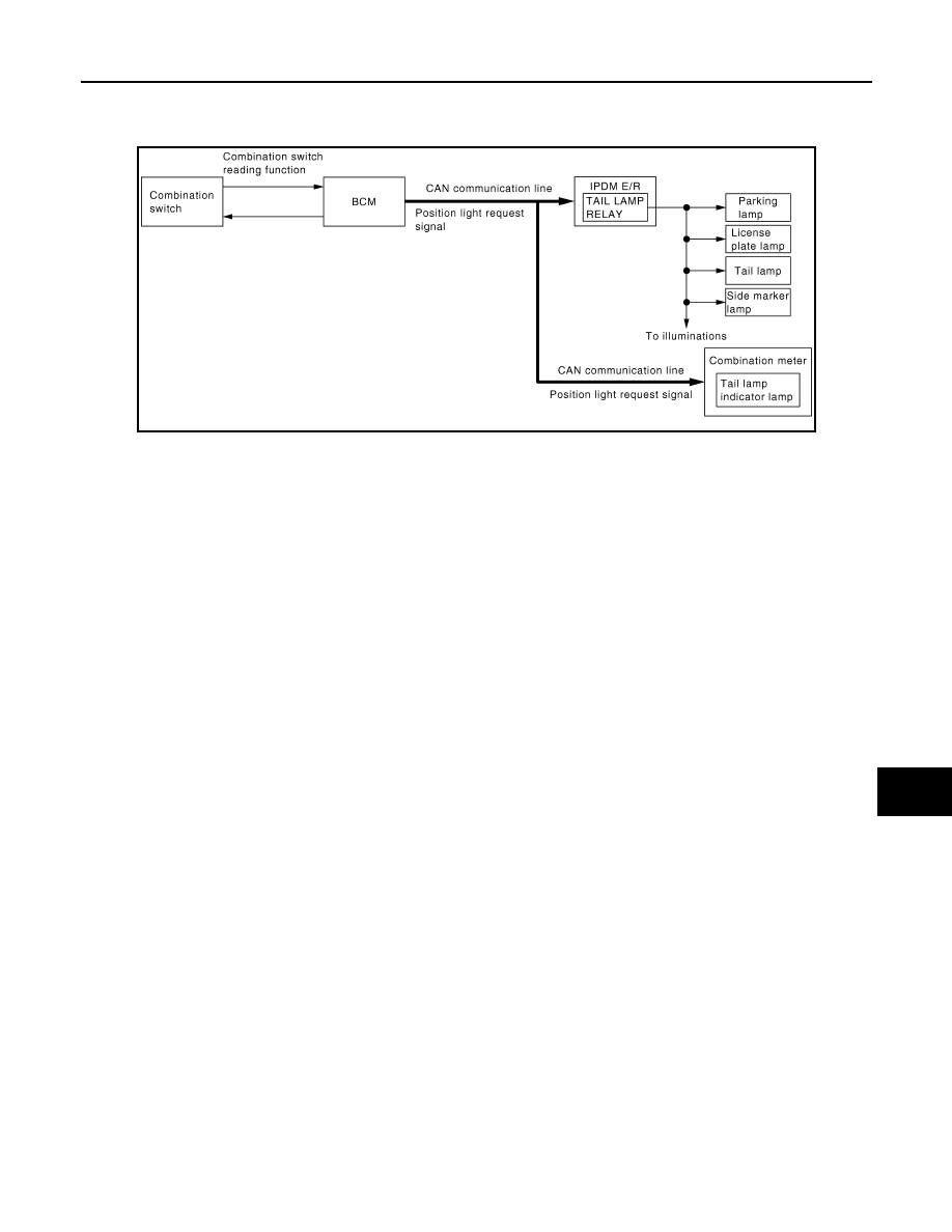
System Diagram
INFOID:0000000009723009
System Description
INFOID:0000000009723010
OUTLINE
Parking, license plate, side marker and tail lamps are controlled by combination switch reading function and
headlamp control function of BCM, and relay control function of IPDM E/R.
PARKING, LICENSE PLATE, SIDE MARKER AND TAIL LAMPS OPERATION
• BCM detects the combination switch condition by the combination switch reading function.
• BCM transmits the position light request signal to IPDM E/R and the combination meter with CAN communi-
cation according to the ON/OFF condition of the parking, license plate, side marker and tail lamps.
Parking, license plate, side marker and tail lamps ON condition
- Lighting switch 1ST
- Lighting switch 2ND
• IPDM E/R turns the integrated tail lamp relay ON and turns the parking lamp, license plate, side marker and
tail lamps ON according to the position light request signal.
• Combination meter turns the tail lamp indicator lamp ON according to the position light request signal.
JPLIA0805GB
Нет комментариевНе стесняйтесь поделиться с нами вашим ценным мнением.
Текст