Nissan Murano. Manual — part 522
EC-198
< DTC/CIRCUIT DIAGNOSIS >
[VQ35DE]
P0128 THERMOSTAT FUNCTION
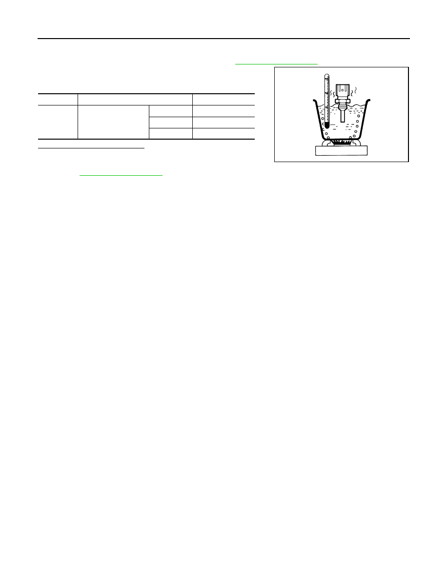
1.
Turn ignition switch OFF.
2.
Disconnect engine coolant temperature sensor harness connector.
3.
Remove engine coolant temperature sensor. Refer to
.
4.
Check resistance between engine coolant temperature sensor
terminals as per the following.
Is the inspection result normal?
YES
>> INSPECTION END
NO
>> Replace engine coolant temperature sensor. Refer to
Terminals
Condition
Resistance (k
Ω
)
1 and 2
Temperature [
°
C (
°
F)]
20 (68)
2.1 - 2.9
50 (122)
0.68 - 1.00
90 (194)
0.236 - 0.260
JMBIA0080ZZ
P0130, P0150 A/F SENSOR 1
EC-199
< DTC/CIRCUIT DIAGNOSIS >
[VQ35DE]
C
D
E
F
G
H
I
J
K
L
M
A
EC
N
P
O
P0130, P0150 A/F SENSOR 1
Description
INFOID:0000000009719945
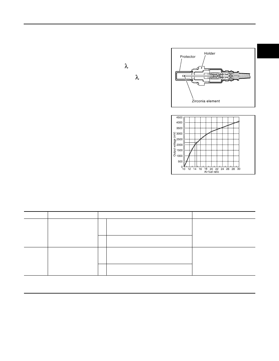
The air fuel ratio (A/F) sensor 1 is a planar one-cell limit current sen-
sor. The sensor element of the A/F sensor 1 is composed an elec-
trode layer, which transports ions. It has a heater in the element.
The sensor is capable of precise measurement = 1, but also in the
lean and rich range. Together with its control electronics, the sensor
outputs a clear, continuous signal throughout a wide range.
The exhaust gas components diffuse through the diffusion layer at
the sensor cell. An electrode layer is applied voltage, and this current
relative oxygen density in lean. Also this current relative hydrocar-
bon density in rich.
Therefore, the A/F sensor 1 is able to indicate air fuel ratio by this
electrode layer of current. In addition, a heater is integrated in the
sensor to ensure the required operating temperature of approxi-
mately 800
°
C (1,472
°
F).
DTC Logic
INFOID:0000000009719946
DTC DETECTION LOGIC
To judge malfunctions, the diagnosis checks that the A/F signal computed by ECM from the A/F sensor 1 sig-
nal fluctuates according to fuel feedback control.
DTC CONFIRMATION PROCEDURE
1.
PRECONDITIONING
If DTC Confirmation Procedure has been previously conducted, always perform the following before conduct-
ing the next test.
1.
Turn ignition switch OFF and wait at least 10 seconds.
2.
Turn ignition switch ON.
3.
Turn ignition switch OFF and wait at least 10 seconds.
TESTING CONDITION:
Before performing the following procedure, confirm that battery voltage is more than 11 V at idle.
>> GO TO 2.
JMBIA0112GB
PBIB3354E
DTC No.
Trouble diagnosis name
DTC detecting condition
Possible cause
P0130
Air fuel ratio (A/F) sensor 1
(bank 1) circuit
A)
The A/F signal computed by ECM from the A/F
sensor 1 signal is constantly in a range other
than approx. 2.2 V.
• Harness or connectors
(The A/F sensor 1 circuit is open
or shorted.)
• A/F sensor 1
B)
The A/F signal computed by ECM from the A/F
sensor 1 signal is constantly approx. 2.2 V.
P0150
Air fuel ratio (A/F) sensor 1
(bank 2) circuit
A)
The A/F signal computed by ECM from the A/F
sensor 1 signal is constantly in a range other
than approx. 2.2 V.
• Harness or connectors
(The A/F sensor 1 circuit is open
or shorted.)
• A/F sensor 1
B)
The A/F signal computed by ECM from the A/F
sensor 1 signal is constantly approx. 2.2 V.

EC-200
< DTC/CIRCUIT DIAGNOSIS >
[VQ35DE]
P0130, P0150 A/F SENSOR 1
2.
PERFORM DTC CONFIRMATION PROCEDURE FOR MALFUNCTION A
1.
Start engine and warm it up to normal operating temperature.
2.
Let engine idle for 2 minutes.
3.
Check 1st trip DTC.
Is 1st trip DTC detected?
YES
>> Go to
NO-1
>> With CONSULT: GO TO 3.
NO-2
>> With GST: GO TO 7.
3.
CHECK AIR FUEL RATIO (A/F) SENSOR 1 FUNCTION
1.
Start engine and warm it up to normal operating temperature.
2.
Select “A/F SEN1 (B1)” or “A/F SEN1 (B2)” in “DATA MONITOR” mode with CONSULT.
3.
Check “A/F SEN1 (B1)” or “A/F SEN1 (B2)” indication.
Does the indication fluctuate around 2.2 V?
YES
>> GO TO 4.
NO
>> Go to
4.
PERFORM DTC CONFIRMATION PROCEDURE FOR MALFUNCTION B-I
1.
Select “A/F SEN1 (B1) P1276” (for DTC P0130) or “A/F SEN1 (B2) P1286” (for DTC P0150) of “A/F
SEN1” in “DTC WORK SUPPORT” mode with CONSULT.
2.
Touch “START”.
3.
When the following conditions are met, “TESTING” will be displayed on the CONSULT screen.
If “TESTING” is not displayed after 20 seconds, retry from step 2.
CAUTION:
Always drive vehicle at a safe speed.
Is “TESTING” displayed on CONSULT screen?
YES
>> GO TO 5.
NO
>> Check A/F sensor 1 function again. GO TO 3.
5.
PERFORM DTC CONFIRMATION PROCEDURE FOR MALFUNCTION B-II
Release accelerator pedal fully.
NOTE:
Never apply brake when releasing the accelerator pedal.
Which does “TESTING” change to?
COMPLETED>>GO TO 6.
OUT OF CONDITION>>Retry DTC CONFIRMATION PROCEDURE. GO TO 4.
6.
PERFORM DTC CONFIRMATION PROCEDURE FOR MALFUNCTION B-III
Touch “SELF-DIAG RESULT”.
Which is displayed on CONSULT screen?
OK
>> INSPECTION END
NG
>> Go to
7.
PERFORM COMPONENT FUNCTION CHECK FOR MALFUNCTION B
Perform component function check. Refer to
EC-201, "Component Function Check"
NOTE:
Use component function check to check the overall function of the A/F sensor 1 circuit. During this check, a
1st trip DTC might not be confirmed.
Is the inspection result normal?
YES
>> INSPECTION END
ENG SPEED
1,000 - 3,200 rpm
VHCL SPEED SE
More than 64 km/h (40 mph)
B/FUEL SCHDL
1.0 - 8.0 msec
Selector lever
D position

P0130, P0150 A/F SENSOR 1
EC-201
< DTC/CIRCUIT DIAGNOSIS >
[VQ35DE]
C
D
E
F
G
H
I
J
K
L
M
A
EC
N
P
O
NO
>> Go to
Component Function Check
INFOID:0000000009719947
1.
PERFORM COMPONENT FUNCTION CHECK
With GST
1.
Start engine and warm it up to normal operating temperature.
2.
Drive the vehicle at a speed of 80 km/h (50 MPH) for a few minutes in the suitable gear position.
3.
Shift the selector lever to the D position, then release the accelerator pedal fully until the vehicle speed
decreases to 50 km/h (31 MPH).
CAUTION:
Always drive vehicle at a safe speed.
NOTE:
Never apply brake when releasing the accelerator pedal.
4.
Repeat steps 2 and 3 for 5 times.
5.
Stop the vehicle and turn ignition switch OFF.
6.
Wait at least 10 seconds and restart engine.
7.
Repeat steps 2 and 3 for 5 times.
8.
Stop the vehicle.
9.
Check 1st trip DTC.
Is 1st trip DTC detected?
YES
>> Go to
NO
>> INSPECTION END
Diagnosis Procedure
INFOID:0000000009719948
1.
CHECK GROUND CONNECTION
1.
Turn ignition switch OFF.
2.
Check ground connection E38. Refer to Ground Inspection in
.
Is the inspection result normal?
YES
>> GO TO 2.
NO
>> Repair or replace ground connection.
2.
CHECK AIR FUEL RATIO (A/F) SENSOR 1 POWER SUPPLY CIRCUIT
1.
Disconnect A/F sensor 1 harness connector.
2.
Turn ignition switch ON.
3.
Check the voltage between A/F sensor 1 harness connector and ground.
Is the inspection result normal?
YES
>> GO TO 4.
NO
>> GO TO 3.
3.
DETECT MALFUNCTIONING PART
Check the following.
• IPDM E/R harness connector F12
• 15 A fuse (No. 46)
• Harness for open or short between A/F sensor 1 and IPDM E/R
>> Repair or replace harness or connectors.
4.
CHECK A/F SENSOR 1 INPUT SIGNAL CIRCUIT FOR OPEN AND SHORT
1.
Turn ignition switch OFF.
2.
Disconnect ECM harness connector.
DTC
A/F sensor 1
Ground
Voltage
Bank
Connector
Terminal
P0130
1
F27
4
Ground
Battery voltage
P0150
2
F64
4
Нет комментариевНе стесняйтесь поделиться с нами вашим ценным мнением.
Текст