Nissan Murano. Manual — part 115
AV-238
< DTC/CIRCUIT DIAGNOSIS >
[BOSE AUDIO WITHOUT NAVIGATION]
U1243 DISPLAY UNIT
U1243 DISPLAY UNIT
DTC Logic
INFOID:0000000009721745
Diagnosis Procedure
INFOID:0000000009721746
1.
CHECK DISPLAY UNIT POWER SUPPLY AND GROUND CIRCUIT
Check display unit power supply and ground circuit. Refer to
AV-244, "DISPLAY UNIT : Diagnosis Procedure"
.
Is the inspection result normal?
YES
>> GO TO 2.
NO
>> Repair malfunctioning parts.
2.
CHECK CONTINUITY COMMUNICATION CIRCUIT
1.
Turn ignition switch OFF.
2.
Disconnect display unit connector and AV control unit connector.
3.
Check continuity between display unit harness connector and AV control unit harness connector.
4.
Check continuity between display unit harness connector and ground.
Is the inspection result normal?
YES
>> GO TO 3.
NO
>> Repair harness or connector.
3.
CHECK COMMUNICATION SIGNAL
1.
Connect display unit connector and AV control unit connector.
2.
Turn ignition switch ON.
3.
Check signal between display unit harness connector and ground.
DTC
Display contents of
CONSULT
DTC detection condition
Possible malfunction factor
U1243
FRONT DISP CONN
[U1243]
When either one of the following items are detected:
• display unit power supply and ground circuits are mal-
functioning.
• serial communication circuits between display unit and
AV control unit are malfunctioning.
• Display unit power supply and
ground circuits.
• Serial communication circuits be-
tween display unit and AV control
unit.
Display unit
AV control unit
Continuity
Connector
Terminals
Connector
Terminals
M194
11
M172
51
Existed
22
39
Display unit
Ground
Continuity
Connector
Terminals
M194
11
Not existed
12
AV
U1243 DISPLAY UNIT
AV-239
< DTC/CIRCUIT DIAGNOSIS >
[BOSE AUDIO WITHOUT NAVIGATION]
C
D
E
F
G
H
I
J
K
L
M
B
A
O
P
Is the inspection result normal?
YES
>> GO TO 4.
NO
>> Replace AV control unit. Refer to
4.
CHECK COMMUNICATION SIGNAL
Check signal between display unit harness connector and ground.
Is the inspection result normal?
YES
>> INSPECTION END
NO
>> Replace display unit. Refer to
.
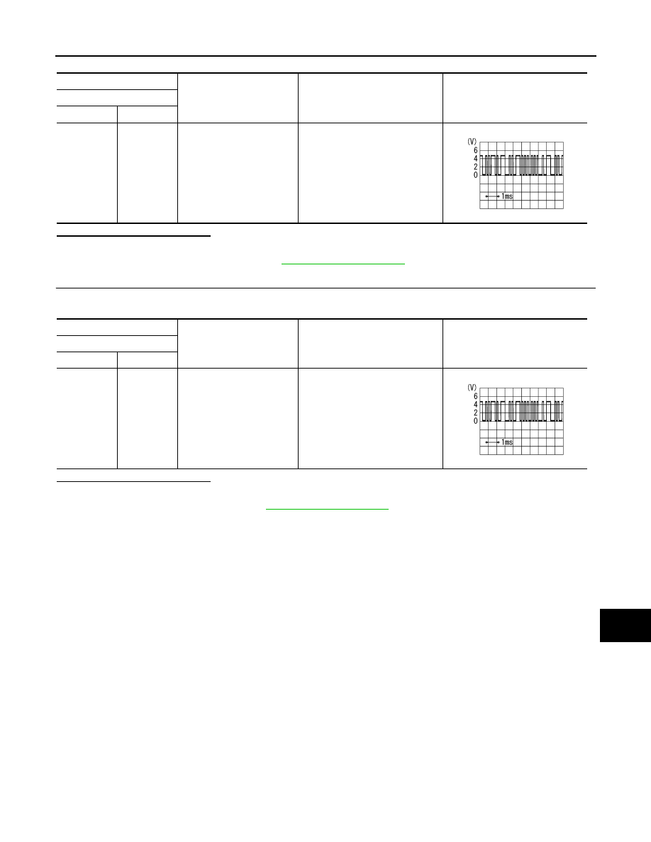
(+)
(
−
)
Condition
Reference value
Display unit
Connector
Terminal
M194
11
Ground
When adjusting display bright-
ness.
PKIB5039J
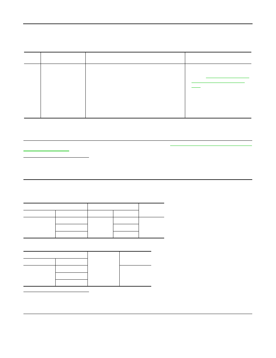
(+)
(
−
)
Condition
Reference value
Display unit
Connector
Terminal
M194
22
Ground
When adjusting display bright-
ness.
PKIB5039J
AV-240
< DTC/CIRCUIT DIAGNOSIS >
[BOSE AUDIO WITHOUT NAVIGATION]
U1255 SATELLITE RADIO TUNER
U1255 SATELLITE RADIO TUNER
DTC Logic
INFOID:0000000009721747
Diagnosis Procedure
INFOID:0000000009721748
1.
CHECK SATELLITE RADIO TUNER POWER SUPPLY AND GROUND CIRCUIT
Check satellite radio tuner power supply and ground circuit. Refer to
AV-246, "SATELLITE RADIO TUNER :
Is the inspection result normal?
YES
>> GO TO 2.
NO
>> Repair malfunctioning parts.
2.
CHECK CONTINUITY COMMUNICATION CIRCUIT AND REQUEST SIGNAL CIRCUIT
1.
Turn ignition switch OFF.
2.
Disconnect AV control unit connector and satellite radio tuner connector.
3.
Check continuity between AV control unit harness connector and satellite radio tuner harness connector.
4.
Check continuity between AV control unit harness connector.
Is the inspection result normal?
YES
>> GO TO 3.
NO
>> Repair harness or connector.
3.
CHECK AV CONTROL UNIT VOLTAGE
1.
Connect AV control unit connector.
2.
Turn ignition switch ON.
3.
Check signal between AV control unit harness connector and ground.
DTC
Display contents of
CONSULT
DTC Detection Condition
Possible causes
U1255
SAT CONN
[U1255]
When either one of the following items is detected:
• satellite radio tuner power supply and ground circuit are
malfunctioning.
• communication circuits between AV control unit and
satellite radio tuner are malfunctioning.
• request signal circuit between AV control unit and sat-
ellite radio tuner are malfunctioning.
• Satellite radio tuner power supply
DIO TUNER : Diagnosis Proce-
dure"
• Communication circuit between AV
control unit and satellite radio tun-
er.
• Request signal circuit between AV
control unit and satellite radio tun-
er.
AV control unit
Satellite radio tuner
Continuity
Connector
Terminals
Connector
Terminals
M176
122
B48
10
Existed
129
8
130
9
AV control unit
Ground
Continuity
Connector
Terminals
M176
122
Not existed
129
130
AV
U1255 SATELLITE RADIO TUNER
AV-241
< DTC/CIRCUIT DIAGNOSIS >
[BOSE AUDIO WITHOUT NAVIGATION]
C
D
E
F
G
H
I
J
K
L
M
B
A
O
P
Is the inspection result normal?
YES
>> GO TO 4.
NO
>> Replace AV control unit. Refer to
4.
CHECK SATELLITE RADIO TUNER VOLTAGE
1.
Turn ignition switch OFF.
2.
Disconnect AV control unit connector.
3.
Connect satellite radio tuner connector.
4.
Turn ignition switch ON.
5.
Check signal between satellite radio tuner harness connector and ground.
Is the inspection result normal?
YES
>> INSPECTION END
NO
>> Replace satellite radio tuner. Refer to
(+)
(
−
)
Voltage
(Approx.)
AV control unit
Connector
Terminals
M176
129
Ground
7.0 V
130
7.0 V
(+)
(
−
)
Voltage
(Approx.)
Satellite radio tuner
Connector
Terminal
B48
10
Ground
7.0 V
Нет комментариевНе стесняйтесь поделиться с нами вашим ценным мнением.
Текст