Nissan Murano. Manual — part 1090

PCS-122
< SYMPTOM DIAGNOSIS >
[POWER DISTRIBUTION SYSTEM]
PUSH-BUTTON IGNITION SWITCH DOES NOT OPERATE
SYMPTOM DIAGNOSIS
PUSH-BUTTON IGNITION SWITCH DOES NOT OPERATE
Description
INFOID:0000000009722687
Check that vehicle is under the condition shown in “Conditions of vehicle” before starting diagnosis, and check
each symptom.
NOTE:
The engine start function, door lock function, power distribution system, and NATS-IVIS/NVIS in the Intelligent
Key system are closely related to each other regarding control. The vehicle security function can operate only
when the door lock and power distribution system are operating normally.
Conditions of Vehicle (Operating Conditions)
• “ENGINE START BY I-KEY” in “WORK SUPPORT” is ON when setting on CONSULT.
• Intelligent Key is not inserted in key slot.
• One or more of Intelligent Keys with registered Intelligent Key ID is in the vehicle.
Diagnosis Procedure
INFOID:0000000009722688
1.
PERFORM WORK SUPPORT
Perform “INSIDE ANT DIAGNOSIS” on Work Support of “INTELLIGENT KEY”.
Refer to
DLK-57, "INTELLIGENT KEY : CONSULT Function (BCM - INTELLIGENT KEY)"
>> GO TO 2.
2.
PERFORM SELF-DIAGNOSTIC RESULT
Perform Self-Diagnostic Result of “BCM”.
Is DTC detected?
YES
>> Refer to
(trunk room).
NO
>> GO TO 3.
3.
CHECK PUSH-BUTTON IGNITION SWITCH
Check push-button ignition switch.
Refer to
PCS-67, "Component Function Check"
Is the operation normal?
YES
>> GO TO 4.
NO
>> Repair or replace malfunctioning parts.
4.
CONFIRM THE OPERATION
Confirm the operation again.
Is the inspection normal?
YES
>> Check intermittent incident. Refer to
GI-44, "Intermittent Incident"
.
NO
>> GO TO 1.

PCS
PUSH-BUTTON IGNITION SWITCH POSITION INDICATOR DOES NOT ILLUMI-
NATE
PCS-123
< SYMPTOM DIAGNOSIS >
[POWER DISTRIBUTION SYSTEM]
C
D
E
F
G
H
I
J
K
L
B
A
O
P
N
PUSH-BUTTON IGNITION SWITCH POSITION INDICATOR DOES NOT IL-
LUMINATE
Description
INFOID:0000000009722689
• Before performing the diagnosis in the following table, check “Work Flow”. Refer to
• Check that vehicle is under the condition shown in “Conditions of vehicle” before starting diagnosis, and
check each symptom.
Conditions of Vehicle (Operating Conditions)
• “ENGINE START BY I-KEY” in “WORK SUPPORT” is ON when setting on CONSULT.
• One or more of Intelligent Keys with registered Intelligent Key ID is in the vehicle.
Diagnosis Procedure
INFOID:0000000009722690
1.
CHECK PUSH-BUTTON IGNITION SWITCH INDICATOR
Check push-button ignition switch indicator.
Refer to
PCS-69, "Component Function Check"
Is the inspection result normal?
YES
>> GO TO 2.
NO
>> Repair or replace the malfunctioning parts.
2.
CONFIRM THE OPERATION
Confirm the operation again.
Is the result normal?
YES
>> Check intermittent incident. Refer to
GI-44, "Intermittent Incident"
.
NO
>> GO TO 1.
PCS-124
< REMOVAL AND INSTALLATION >
[POWER DISTRIBUTION SYSTEM]
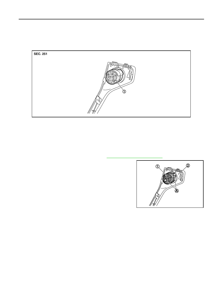
PUSH-BUTTON IGNITION SWITCH
REMOVAL AND INSTALLATION
PUSH-BUTTON IGNITION SWITCH
Exploded View
INFOID:0000000009722691
Removal and Installation
INFOID:0000000009722692
REMOVAL
1.
Remove the instrument stay cover LH. Refer to
IP-15, "Removal and Installation"
2.
Remove the push-button ignition switch (1) from instrument stay
cover LH, after removing pawl (A). Press push-button ignition
switch (1) back to disengage from instrument stay cover LH (2).
INSTALLATION
Install in the reverse order of removal.
1.
Push-button ignition switch
JMKIA1812ZZ
JMKIA1813ZZ
PG
PG-1
ELECTRICAL & POWER CONTROL
C
D
E
F
G
H
I
J
K
L
B
SECTION
PG
A
O
P
N
CONTENTS
POWER SUPPLY, GROUND & CIRCUIT ELEMENTS
POWER SUPPLY&GROUND CIRCUIT
BASIC INSPECTION . . . . . . . . .
BATTERY . . . . . . . . . . . . . . .
How to Handle Battery . . . . . . . . . . . ..
Work Flow . . . . . . . . . . . . . . . .....
DTC/CIRCUIT DIAGNOSIS . . . . . . ..
POWER SUPPLY ROUTING CIRCUIT . . . ...
Wiring Diagram - BATTERY POWER SUPPLY - . ..
Wiring Diagram - BATTERY POWER SUPPLY
FUSIBLE LINK No. L - . . . . . . . . . . .
Wiring Diagram - BATTERY POWER SUPPLY
FUSE No. 6 - . . . . . . . . . . . . . . ...
Wiring Diagram - BATTERY POWER SUPPLY
FUSE No. 9 - . . . . . . . . . . . . . . ...
Wiring Diagram - BATTERY POWER SUPPLY
FUSE No. 11 - . . . . . . . . . . . . . . .
Wiring Diagram - BATTERY POWER SUPPLY
FUSE No. 35 - . . . . . . . . . . . . . . .
Wiring Diagram - BATTERY POWER SUPPLY
FUSE No. 50 - . . . . . . . . . . . . . . .
Wiring Diagram - BATTERY POWER SUPPLY
FUSE No. 52 - . . . . . . . . . . . . . . .
Wiring Diagram - BATTERY POWER SUPPLY
FUSE No. 53 - . . . . . . . . . . . . . . .
Wiring Diagram - ACCESSORY POWER SUP-
PLY - . . . . . . . . . . . . . . . . . ...
Wiring Diagram - ACCESSORY POWER SUP-
PLY FUSE No. 19 - . . . . . . . . . . . . .
Wiring Diagram - IGNITION POWER SUPPLY - .
Wiring Diagram - IGNITION POWER SUPPLY
FUSE No. 3 - . . . . . . . . . . . . . . ...
Wiring Diagram - IGNITION POWER SUPPLY
FUSE No. 4 - . . . . . . . . . . . . . . ...
Wiring Diagram - IGNITION POWER SUPPLY
FUSE No. 44 - . . . . . . . . . . . . . . .
Wiring Diagram - IGNITION POWER SUPPLY
FUSE No. 47 - . . . . . . . . . . . . . . .
Fuse . . . . . . . . . . . . . . . . . . .
Fusible Link . . . . . . . . . . . . . . . .
Circuit Breaker . . . . . . . . . . . . . . .
OPTION HARNESS . . . . . . . . . . ..
Wiring Diagram - OPTION HARNESS - . . . . ..
HARNESS LAYOUT . . . . . . . . . . .
Outline . . . . . . . . . . . . . . . . . .
Engine Room Harness . . . . . . . . . . .
Engine Control Harness . . . . . . . . . . ..
Main Harness . . . . . . . . . . . . . . ..
Body Harness . . . . . . . . . . . . . . ..
Door Harness . . . . . . . . . . . . . . ..
Room Lamp Harness . . . . . . . . . . . ...
HARNESS CONNECTOR . . . . . . . . .
Description . . . . . . . . . . . . . . . ...
STANDARDIZED RELAY . . . . . . . . .
Description . . . . . . . . . . . . . . . ...
FUSE BLOCK - JUNCTION BOX (J/B) . . .
Fuse, Connector and Terminal Arrangement . . ..
FUSE, FUSIBLE LINK AND RELAY BOX . .
Fuse and Fusible Link Arrangement . . . . . .
IPDM E/R (INTELLIGENT POWER DISTRI-
BUTION MODULE ENGINE ROOM) . . . .
Fuse, Connector and Terminal Arrangement . . ..
PRECAUTION . . . . . . . . . . . ..
PRECAUTIONS . . . . . . . . . . . . .
FOR USA AND CANADA . . . . . . . . . . ..
FOR USA AND CANADA : Precautions for Re-
moving of Battery Terminal . . . . . . . . . ..
Нет комментариевНе стесняйтесь поделиться с нами вашим ценным мнением.
Текст