Nissan Murano. Manual — part 879
INL-28
< DTC/CIRCUIT DIAGNOSIS >
PUSH-BUTTON IGNITION SWITCH ILLUMINATION CIRCUIT
Is the measurement value normal?
YES
>> GO TO 4.
NO
>> GO TO 5.
4.
CHECK PUSH-BUTTON IGNITION SWITCH ILLUMINATION POWER SUPPLY OPEN CIRCUIT
1.
Turn the ignition switch OFF.
2.
Disconnect BCM connector and the push-button ignition switch connector.
3.
Check continuity between BCM harness connector and the push-button ignition switch harness connector.
Does the continuity exist?
YES
>> Replace push-button ignition switch.
NO
>> Repair the harness or the connector.
5.
CHECK PUSH-BUTTON IGNITION SWITCH ILLUMINATION POWER SUPPLY SHORT CIRCUIT
1.
Turn the ignition switch OFF.
2.
Disconnect BCM connector and the push-button ignition switch connector.
3.
Check continuity between BCM harness connector and the ground.
Does the continuity exist?
YES
>> Repair the harness or the connector.
NO
>> Replace BCM.
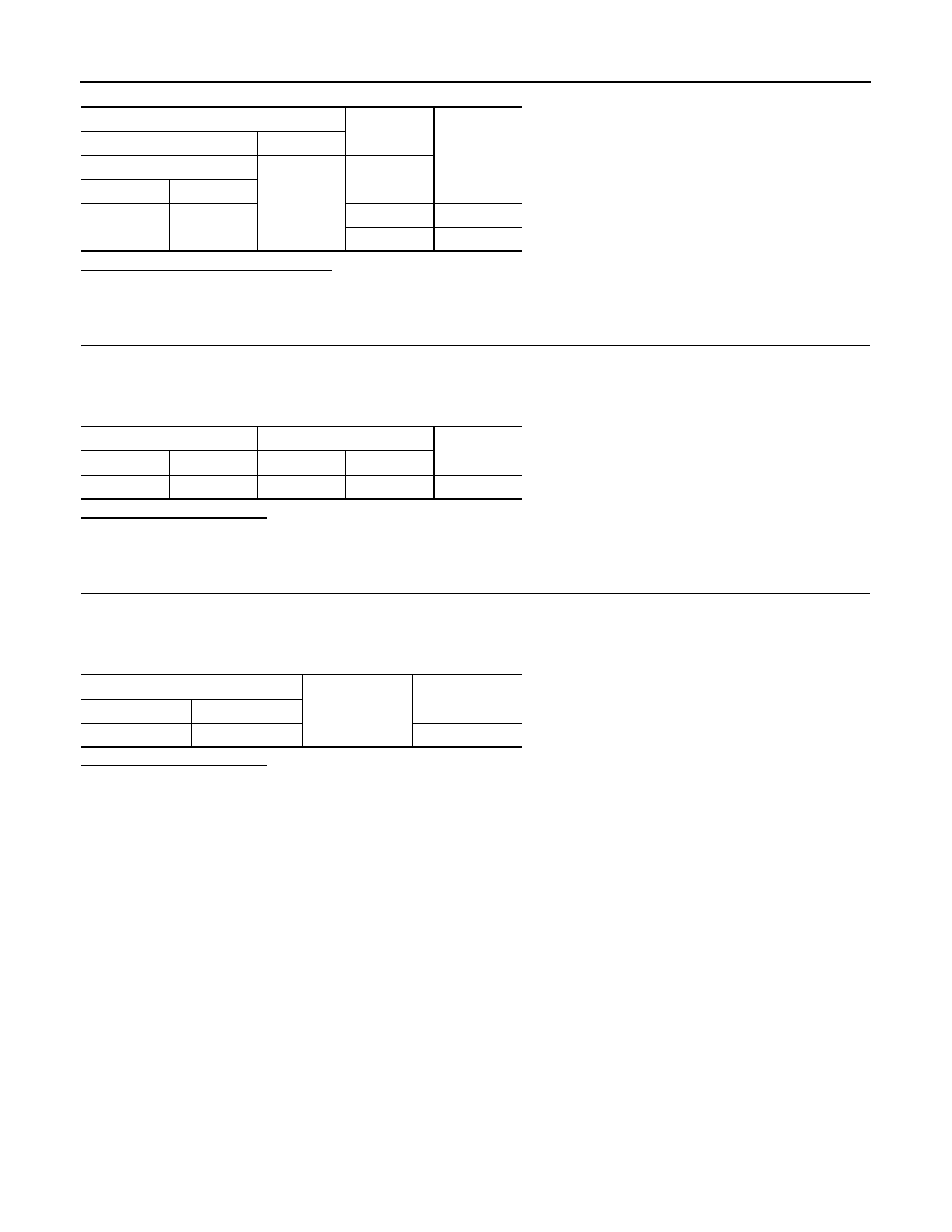
Terminals
Test item
Voltage (Ap-
prox.)
(+)
(–)
BCM
Ground
ENGINE SW
ILLUMI
Connector
Terminal
M123
133
ON
5 V
OFF
0 V
BCM
Push-button ignition switch
Continuity
Connector
Terminal
Connector
Terminal
M123
133
M101
3
Existed
BCM
Ground
Continuity
Connector
Terminal
M123
133
Not existed
INTERIOR ROOM LAMP CONTROL SYSTEM
INL-29
< DTC/CIRCUIT DIAGNOSIS >
C
D
E
F
G
H
I
J
K
M
A
B
INL
N
O
P
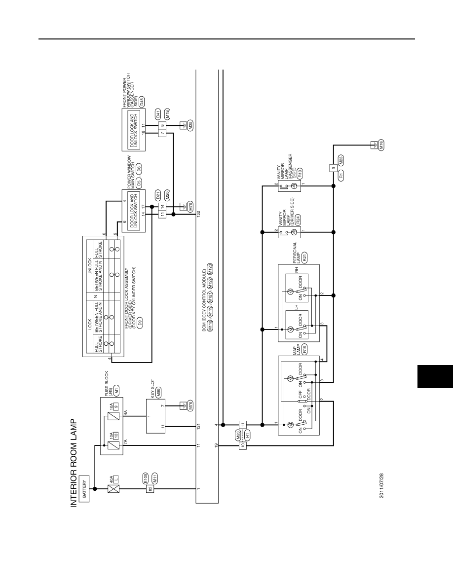
INTERIOR ROOM LAMP CONTROL SYSTEM
Wiring Diagram - INTERIOR ROOM LAMP -
INFOID:0000000009718427
JRLWC1096GB
INL-30
< DTC/CIRCUIT DIAGNOSIS >
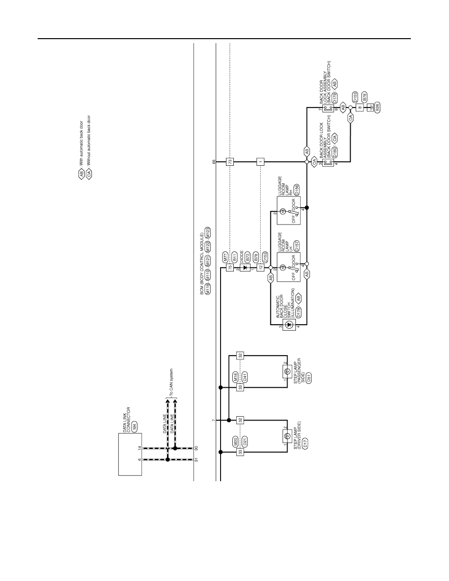
INTERIOR ROOM LAMP CONTROL SYSTEM
JRLWC1097GB
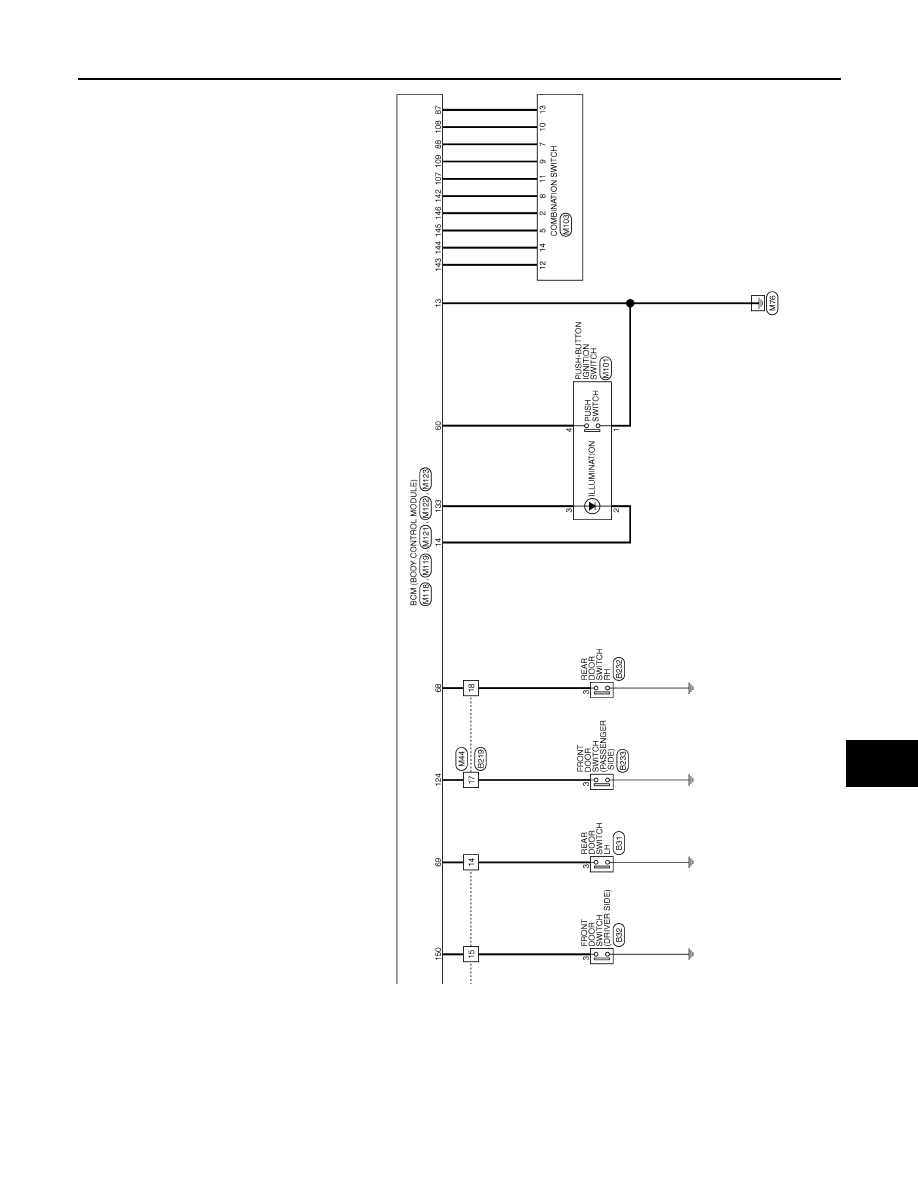
INTERIOR ROOM LAMP CONTROL SYSTEM
INL-31
< DTC/CIRCUIT DIAGNOSIS >
C
D
E
F
G
H
I
J
K
M
A
B
INL
N
O
P
JRLWC1098GB
Нет комментариевНе стесняйтесь поделиться с нами вашим ценным мнением.
Текст