Nissan Murano. Manual — part 497
EC-98
< SYSTEM DESCRIPTION >
[VQ35DE]
EVAPORATIVE EMISSION SYSTEM
JMBIA1832GB
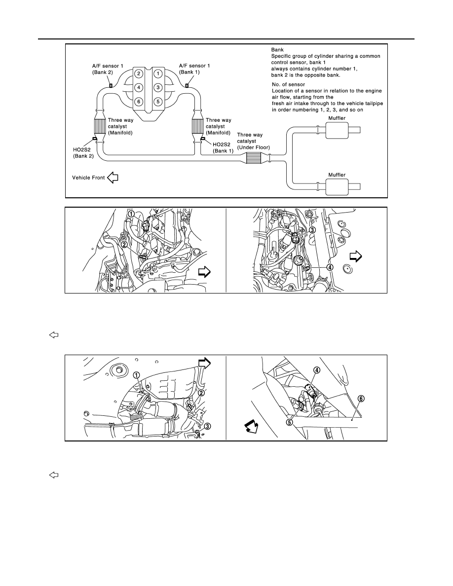
1.
A/F sensor 1 (bank 1) harness con-
nector
2.
A/F sensor 1 (bank 1)
3.
A/F sensor 1 (bank 2) harness con-
nector
4.
A/F sensor 1 (bank 2)
: Vehicle front
1.
HO2S2 (bank 1)
2.
HO2S2 (bank 2)
3.
HO2S2 (bank 2) harness connector
4.
HO2S2 (bank 1) harness connector
5.
Power steering pressure sensor
6.
Drive shaft (RH)
: Vehicle front
JMBIA1116ZZ
JMBIA1117ZZ
EVAPORATIVE EMISSION SYSTEM
EC-99
< SYSTEM DESCRIPTION >
[VQ35DE]
C
D
E
F
G
H
I
J
K
L
M
A
EC
N
P
O
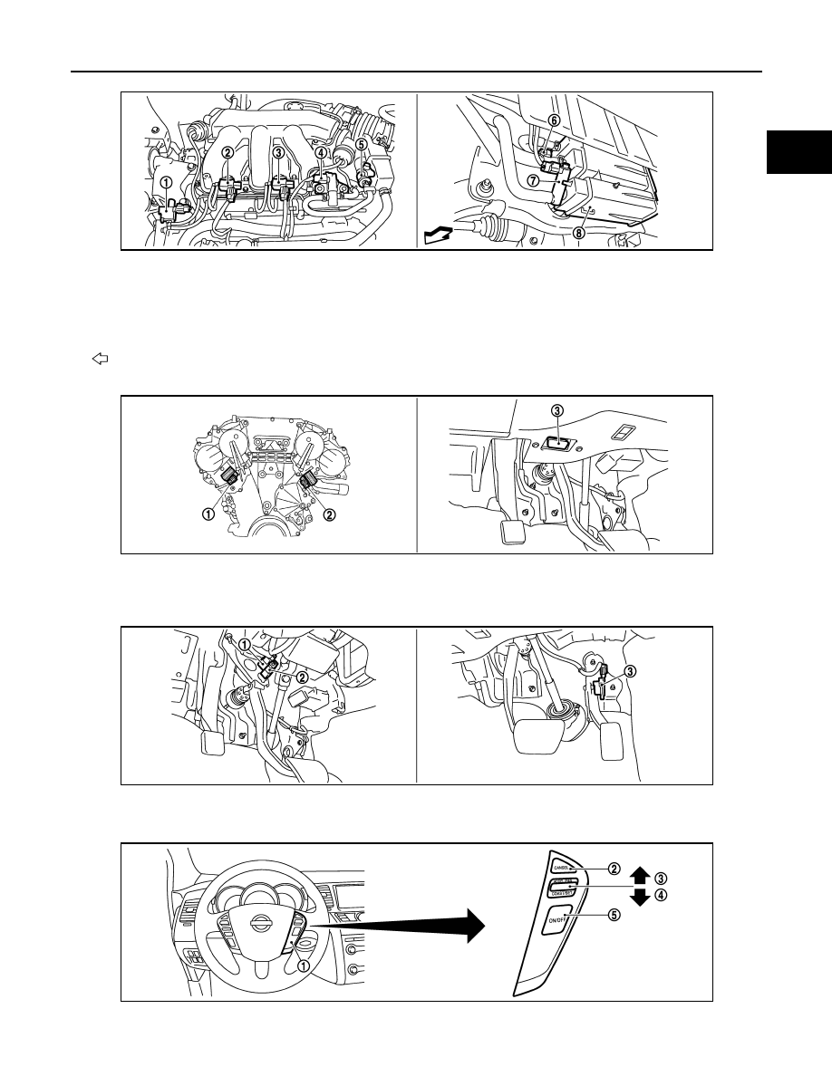
1.
Electronic controlled engine mount
control solenoid valve
2.
VIAS control solenoid valve 1
3.
VIAS control solenoid valve 2
4.
EVAP canister purge volume control
solenoid valve
5.
EVAP service port
6.
EVAP control system pressure sen-
sor
7.
EVAP canister vent control valve
8.
EVAP canister
: Vehicle front
1.
Intake valve timing control solenoid
valve (bank 1)
2.
Intake valve timing control solenoid
valve (bank 2)
3.
Data link connector
1.
Stop lamp switch
2.
ASCD brake switch
3.
Accelerator pedal position sensor
JMBIA1111ZZ
JMBIA1118ZZ
JMBIA1119ZZ
JMBIA1120ZZ
EC-100
< SYSTEM DESCRIPTION >
[VQ35DE]
EVAPORATIVE EMISSION SYSTEM
Component Description
INFOID:0000000009719854
1.
ASCD steering switch
2.
CANSEL switch
3.
RESUME/ACCELERATE switch
4.
SET/COAST switch
5.
MAIN switch
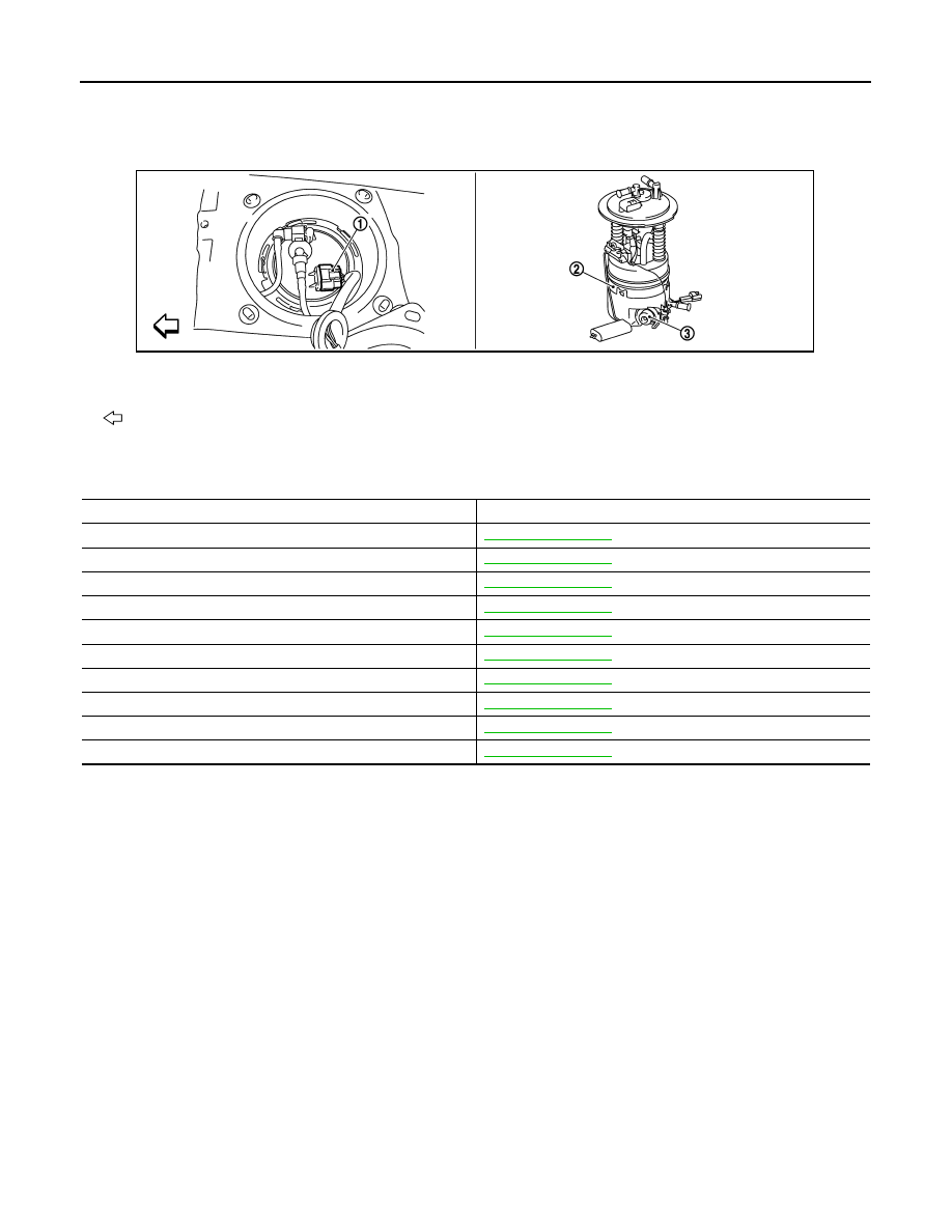
1.
Fuel level sensor unit and fuel pump
harness connector
2.
Fuel level sensor unit and fuel pump 3.
Fuel pressure regulator
: Vehicle front
JMBIA1121ZZ
Component
Reference
A/F sensor 1
Accelerator pedal position sensor
Camshaft position sensor (PHASE)
Crankshaft position sensor (POS)
Engine coolant temperature sensor
EVAP canister purge volume control solenoid valve
EVAP control system pressure sensor
Fuel tank temperature sensor
Mass air flow sensor
Throttle position sensor
INTAKE VALVE TIMING CONTROL
EC-101
< SYSTEM DESCRIPTION >
[VQ35DE]
C
D
E
F
G
H
I
J
K
L
M
A
EC
N
P
O
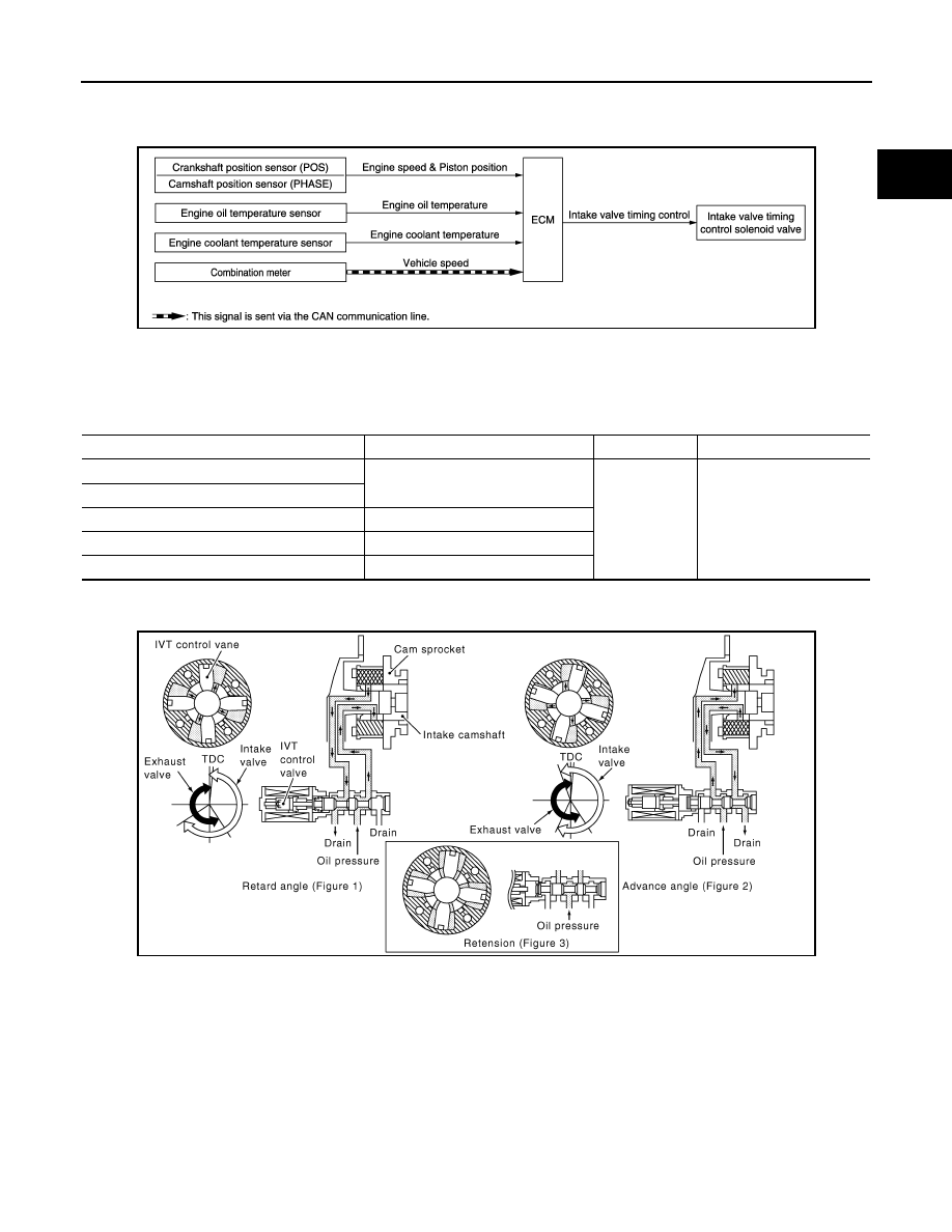
INTAKE VALVE TIMING CONTROL
System Diagram
INFOID:0000000009719855
System Description
INFOID:0000000009719856
INPUT/OUTPUT SIGNAL CHART
*: This signal is sent to the ECM via the CAN communication line
SYSTEM DESCRIPTION
This mechanism hydraulically controls cam phases continuously with the fixed operating angle of the intake
valve.
The ECM receives signals such as crankshaft position, camshaft position, engine speed, and engine coolant
temperature. Then, the ECM sends ON/OFF pulse duty signals to the intake valve timing (IVT) control sole-
noid valve depending on driving status. This makes it possible to control the shut/open timing of the intake
valve to increase engine torque in low/mid speed range and output in high-speed range.
JMBIA1830GB
Sensor
Input signal to ECM
ECM function
Actuator
Crankshaft position sensor (POS)
Engine speed and piston position
Intake valve
timing control
Intake valve timing control
solenoid valve
Camshaft position sensor (PHASE)
Engine oil temperature sensor
Engine oil temperature
Engine coolant temperature sensor
Engine coolant temperature
Combination meter
Vehicle speed*
JMBIA0060GB
Нет комментариевНе стесняйтесь поделиться с нами вашим ценным мнением.
Текст