Nissan Murano. Manual — part 810
HAC-14
< SYSTEM DESCRIPTION >
[WITHOUT 7 INCH DISPLAY]
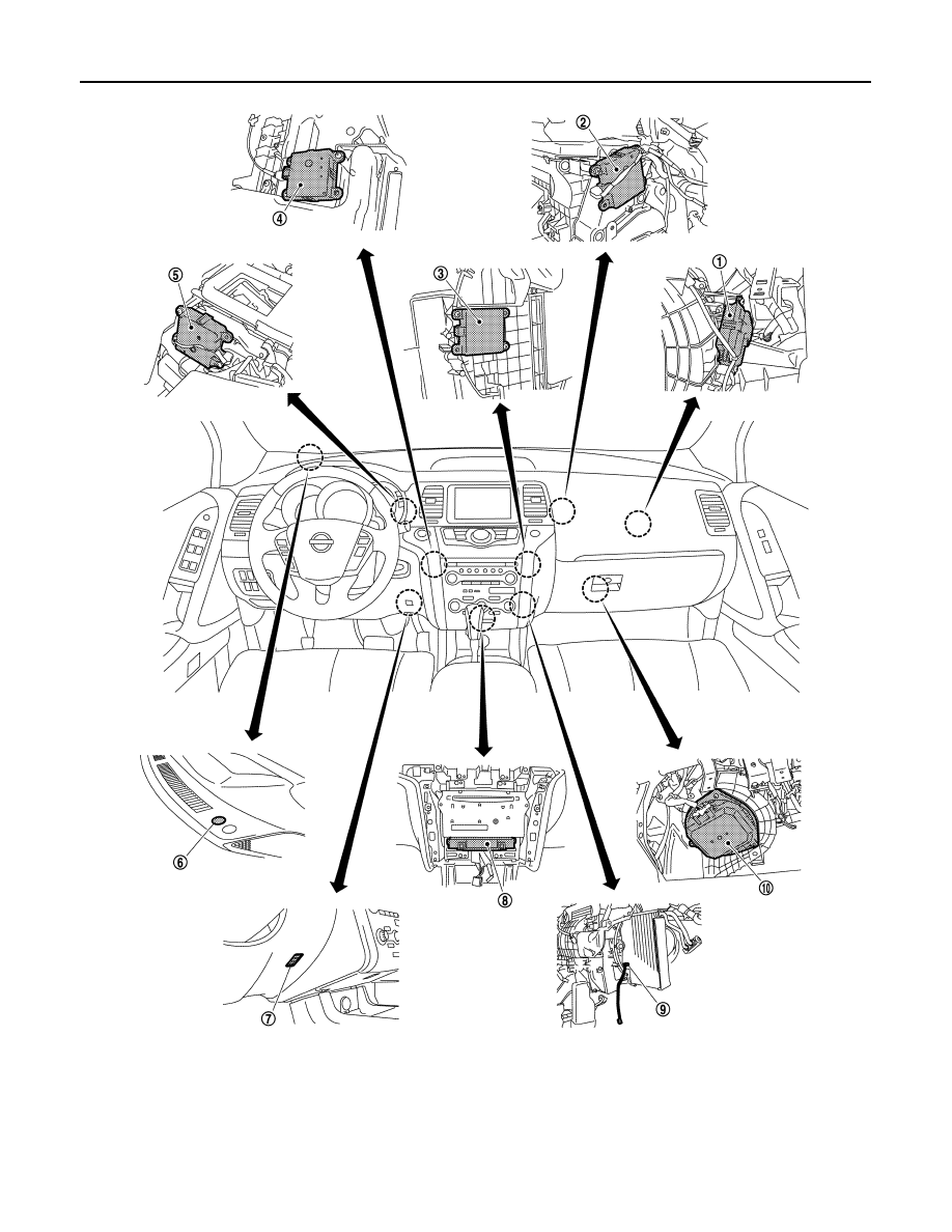
COMPRESSOR CONTROL FUNCTION
1.
Intake door motor
2.
Upper ventilator door motor
3.
Air mix door motor (passenger side)
4.
Air mix door motor (driver side)
5.
Mode door motor
6.
Sunload sensor
7.
In-vehicle sensor
8.
A/C auto amp.
9.
Intake sensor
10. Blower motor
JPIIA0608ZZ
COMPRESSOR CONTROL FUNCTION
HAC-15
< SYSTEM DESCRIPTION >
[WITHOUT 7 INCH DISPLAY]
C
D
E
F
G
H
J
K
L
M
A
B
HAC
N
O
P
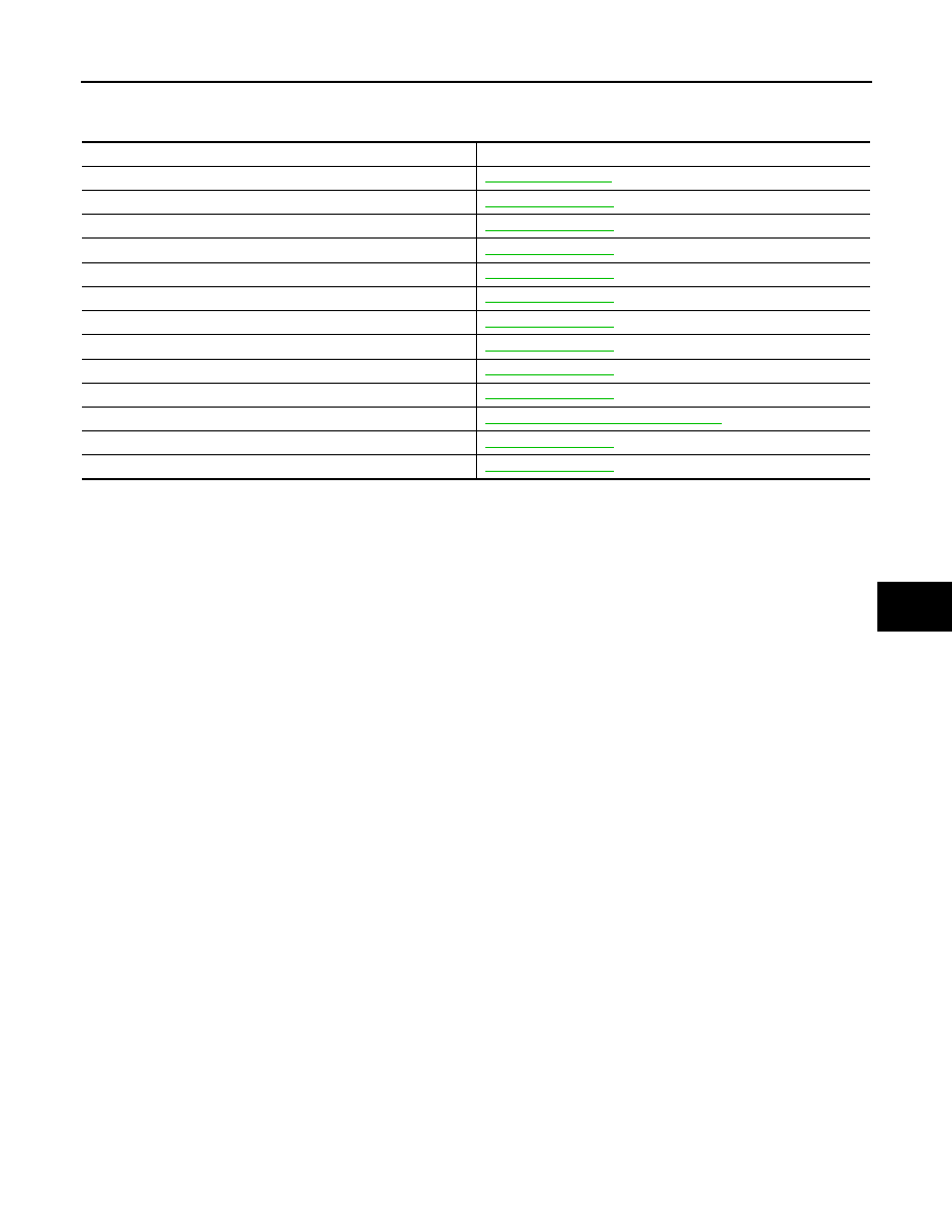
Component’s Role
INFOID:0000000009722032
Component
Reference
Refrigerant pressure sensor
Compressor
Ambient sensor
Intake door motor
Upper ventilator door motor
Air mix door motor (driver side)
Air mix door motor (passenger side)
Mode door motor
Sunload sensor
In-vehicle sensor
A/C auto amp.
HAC-77, "A/C AUTO AMP. : Description"
Intake sensor
Blower motor
HAC-16
< SYSTEM DESCRIPTION >
[WITHOUT 7 INCH DISPLAY]
AUTOMATIC AIR CONDITIONER SYSTEM
AUTOMATIC AIR CONDITIONER SYSTEM
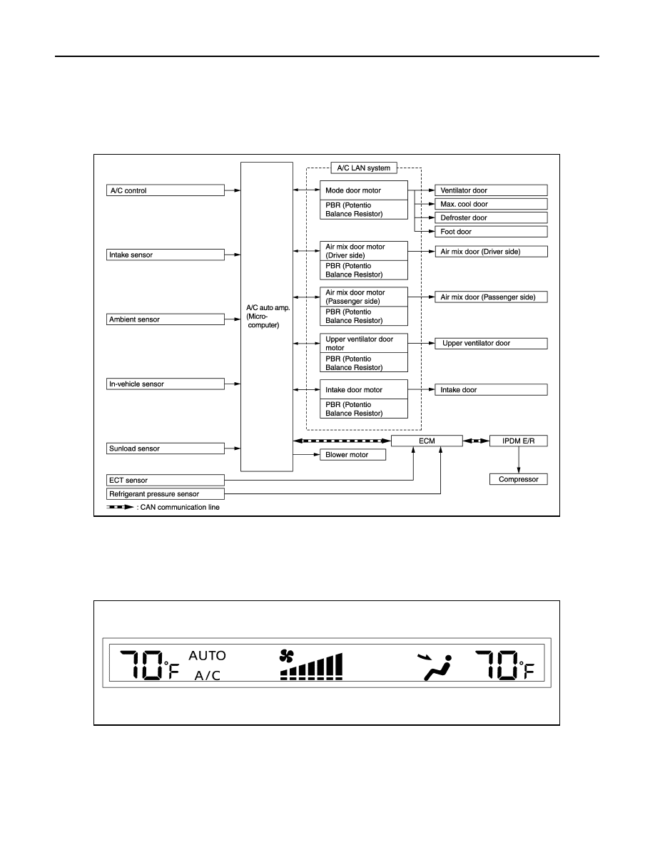
System Diagram
INFOID:0000000009722033
CONTROL SYSTEM
The control system consists of input sensors, switches, the A/C auto amp. (microcomputer) and outputs. The
relationship of these components is as shown in the figure below:
System Description
INFOID:0000000009722034
CONTROL OPERATION
Display
The operation status of the system is displayed on the screen.
JSIIA1539GB
JPIIA0606ZZ
AUTOMATIC AIR CONDITIONER SYSTEM
HAC-17
< SYSTEM DESCRIPTION >
[WITHOUT 7 INCH DISPLAY]
C
D
E
F
G
H
J
K
L
M
A
B
HAC
N
O
P
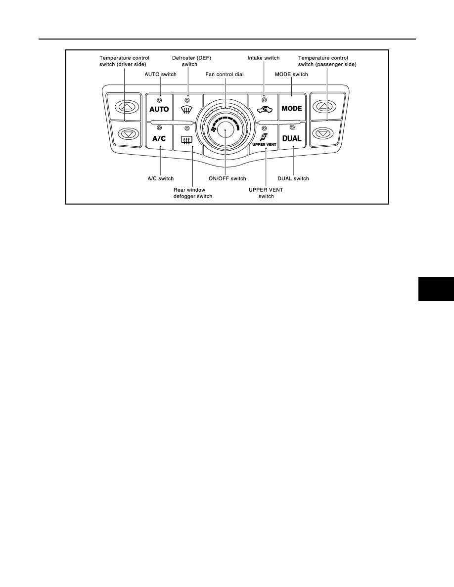
A/C Control
MODE Switch
The air discharge outlets are controlled with this switch.
Temperature Control Switch (Driver Side)
The set temperature is increased or decreased with this switch.
Temperature Control Switch (Passenger Side)
• The set temperature is increased or decreased with this switch.
• When this switch is pressed, DUAL switch indicator is turned ON.
AUTO Switch
• The compressor, intake doors, air mix doors, mode doors and blower speed are automatically controlled so
that the in-vehicle temperature will reach, and be maintained at the set temperature selected by the operator.
• When pressing the AUTO switch, air inlet, air outlet, fan speed, and discharge air temperature are automati-
cally controlled.
Defroster (DEF) Switch
Mode doors are set to the defrost position with this switch. Also, intake doors are set to the outside air position,
and compressor turns ON.
UPPER VENT Switch
• When the UPPER VENT switch is pressed, the UPPER VENT switch indicator is turned ON.
• When the UPPER VENT switch indicator is turned ON, the UPPER VENT switch indicator is turned OFF by
pressing the defroster (DEF) switch (after the above operation, the UPPER VENT switch indicator is turned
ON by pressing the UPPER VENT switch).
A/C Switch
Compressor turns ON or OFF with this switch.
(Pressing the A/C switch when the A/C switch is ON turns OFF the A/C switch and compressor.)
Fan Control Dial
The blower speed is manually controlled with this dial. Seven speeds are available for manual control (as
shown on the display screen).
ON/OFF Switch
Compressor and blower turn OFF, air inlet sets to FRE, and mode the position is set to foot position.
Rear Window Defogger Switch
When indicator is ON, rear window is defogged.
Intake Switch
• When the intake switch is ON, the intake switch indicator is turned ON, and air inlet is set to REC.
• When the intake switch is pressed again, the intake switch indicator is turned OFF, and air inlet is set to FRE.
• When the intake switch is pressed for approximately 1.5 seconds or longer, the intake switch indicator blink
twice. Then, automatic control mode is entered. Inlet status is displayed by indicator even when automati-
cally controlled.
JMIIA0485GB
Нет комментариевНе стесняйтесь поделиться с нами вашим ценным мнением.
Текст