Nissan Murano. Manual — part 588
EC-462
< DTC/CIRCUIT DIAGNOSIS >
[VQ35DE]
ON BOARD REFUELING VAPOR RECOVERY (ORVR)
3.
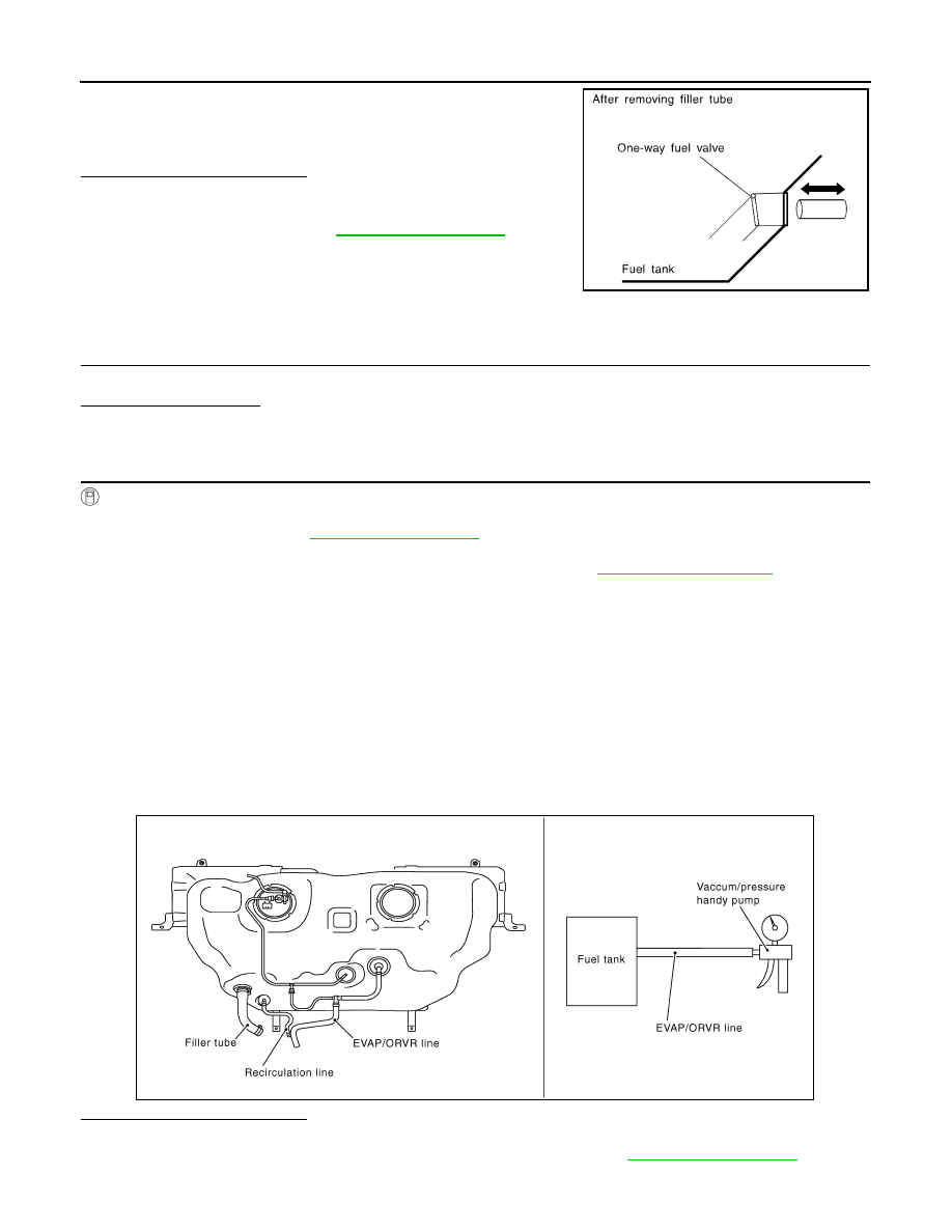
Check one-way fuel valve for operation as per the following.
When a stick is inserted, the valve should open, when removing
stick it should close.
Do not drop any material into the tank.
Is the inspection result normal?
YES
>> INSPECTION END
NO
>> Replace fuel filler tube or replace one-way fuel valve
with fuel tank. Refer to
Component Inspection
INFOID:0000000009720231
1.
INSPECTION START
Will CONSULT be used?
Will CONSULT be used?
YES
>> GO TO 2.
NO
>> GO TO 3.
2.
CHECK REFUELING EVAP VAPOR CUT VALVE
With CONSULT
1.
Turn ignition switch OFF.
2.
Remove fuel tank. Refer to
.
3.
Drain fuel from the tank as per the following:
-
Remove fuel feed hose located on the fuel gauge retainer. Refer to
.
-
Connect a spare fuel hose, one side to fuel gauge retainer where the hose was removed and the other
side to a fuel container.
-
Drain fuel using “FUEL PUMP RELAY” in “ACTIVE TEST” mode with CONSULT.
4.
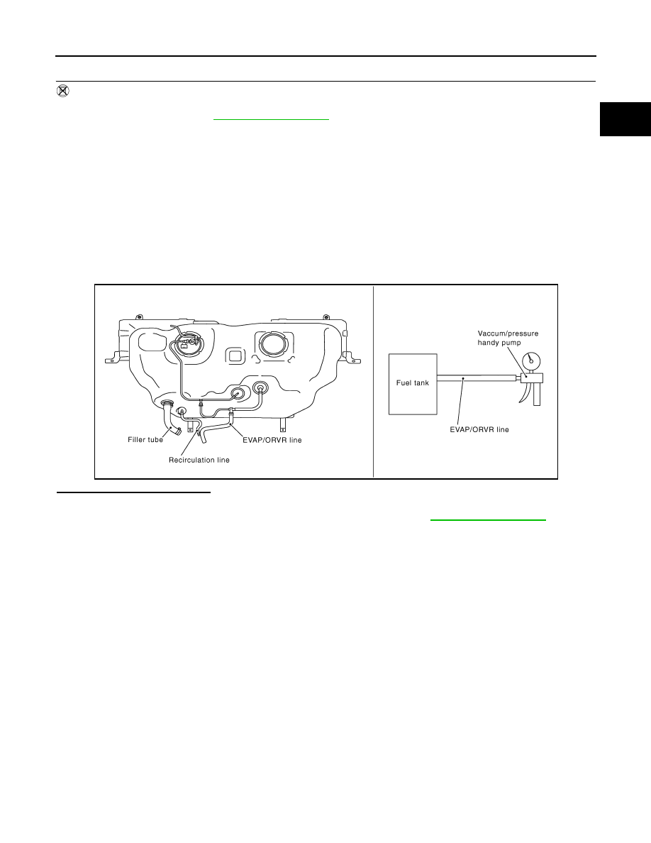
Check refueling EVAP vapor cut valve for being stuck to close as per the following.
Blow air into the refueling EVAP vapor cut valve (from the end of EVAP/ORVR line hose), and check that
the air flows freely into the tank.
5.
Check refueling EVAP vapor cut valve for being stuck to open as per the following.
-
Connect vacuum pump to hose end.
-
Remove fuel gauge retainer with fuel gauge unit.
Always replace O-ring with new one.
-
Turn fuel tank upside down.
-
Apply vacuum pressure to hose end [
−
13.3 kPa (
−
0.136 kg/cm
3
,
−
1.93 psi)] with fuel gauge retainer
remaining open and check that the pressure is applicable.
Is the inspection result normal?
YES
>> INSPECTION END
NO
>> Replace refueling EVAP vapor cut valve with fuel tank. Refer to
SEF665U
JMBIA1126GB
ON BOARD REFUELING VAPOR RECOVERY (ORVR)
EC-463
< DTC/CIRCUIT DIAGNOSIS >
[VQ35DE]
C
D
E
F
G
H
I
J
K
L
M
A
EC
N
P
O
3.
CHECK REFUELING EVAP VAPOR CUT VALVE
Without CONSULT
1.
Turn ignition switch OFF.
2.
Remove fuel tank. Refer to
.
3.
Drain fuel from the tank as per the following:
-
Remove fuel gauge retainer.
-
Drain fuel from the tank using a handy pump into a fuel container.
4.
Check refueling EVAP vapor cut valve for being stuck to close as per the following.
Blow air into the refueling EVAP vapor cut valve (from the end of EVAP/ORVR line hose), and check that
the air flows freely into the tank.
5.
Check refueling EVAP vapor cut valve for being stuck to open as per the following.
-
Connect vacuum pump to hose end.
-
Remove fuel gauge retainer with fuel gauge unit.
Always replace O-ring with new one.
-
Turn fuel tank upside down.
-
Apply vacuum pressure to hose end [
−
13.3 kPa (
−
0.136 kg/cm
3
,
−
1.93 psi)] with fuel gauge retainer
remaining open and check that the pressure is applicable.
Is the inspection result normal?
YES
>> INSPECTION END
NO
>> Replace refueling EVAP vapor cut valve with fuel tank. Refer to
.
JMBIA1126GB
EC-464
< DTC/CIRCUIT DIAGNOSIS >
[VQ35DE]
POSITIVE CRANKCASE VENTILATION
POSITIVE CRANKCASE VENTILATION
Description
INFOID:0000000009720232
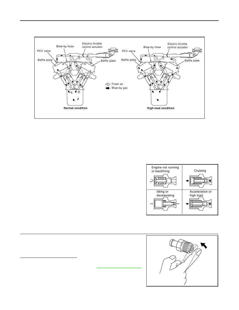
This system returns blow-by gas to the intake manifold.
The positive crankcase ventilation (PCV) valve is provided to conduct crankcase blow-by gas to the intake
manifold.
During partial throttle operation of the engine, the intake manifold sucks the blow-by gas through the PCV
valve.
Normally, the capacity of the valve is sufficient to handle any blow-by and a small amount of ventilating air.
The ventilating air is drawn from the air inlet tubes into the crankcase. In this process the air passes through
the hose connecting air inlet tubes to rocker cover.
Under full-throttle condition, the manifold vacuum is insufficient to draw the blow-by flow through the valve.
The flow goes through the hose connection in the reverse direction.
On vehicles with an excessively high blow-by, the valve does not
meet the requirement. This is because some of the flow will go
through the hose connection to the air inlet tubes under all condi-
tions.
Component Inspection
INFOID:0000000009720233
1.
CHECK PCV VALVE
With engine running at idle, remove PCV valve from rocker cover. A
properly working valve makes a hissing noise as air passes through
it. A strong vacuum should be felt immediately when a finger is
placed over valve inlet.
Is the inspection result normal?
YES
>> INSPECTION END
NO
>> Replace PCV valve. Refer to .
SEC921C
PBIB1588E
PBIB1589E
REFRIGERANT PRESSURE SENSOR
EC-465
< DTC/CIRCUIT DIAGNOSIS >
[VQ35DE]
C
D
E
F
G
H
I
J
K
L
M
A
EC
N
P
O
REFRIGERANT PRESSURE SENSOR
Description
INFOID:0000000009720234
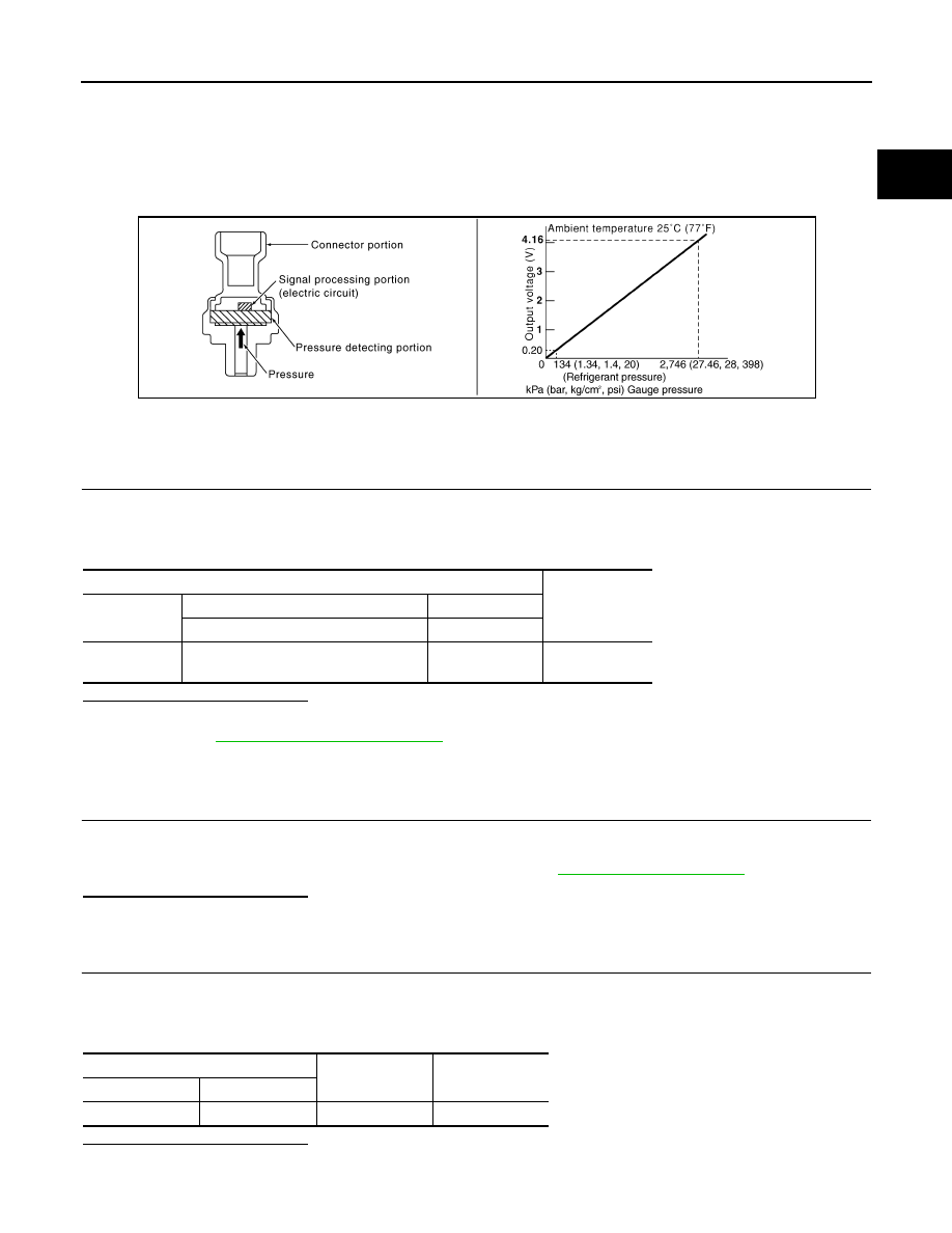
The refrigerant pressure sensor is installed at the condenser of the air conditioner system. The sensor uses an
electrostatic volume pressure transducer to convert refrigerant pressure to voltage. The voltage signal is sent
to ECM, and ECM controls cooling fan system.
Component Function Check
INFOID:0000000009720235
1.
CHECK REFRIGERANT PRESSURE SENSOR FUNCTION
1.
Start engine and warm it up to normal operating temperature.
2.
Turn A/C switch and blower fan switch ON.
3.
Check the voltage between ECM harness connector terminals under the following conditions.
Is the inspection result normal?
YES
>> INSPECTION END
NO
>> Go to
Diagnosis Procedure
INFOID:0000000009720236
1.
CHECK GROUND CONNECTION
1.
Turn A/C switch and blower fan switch OFF.
2.
Turn ignition switch OFF.
3.
Check ground connection E38. Refer to Ground Inspection in
.
Is the inspection result normal?
YES
>> GO TO 2.
NO
>> Repair or replace ground connection.
2.
CHECK REFRIGERANT PRESSURE SENSOR POWER SUPPLY CIRCUIT
1.
Disconnect refrigerant pressure sensor harness connector.
2.
Turn ignition switch ON.
3.
Check the voltage between refrigerant pressure sensor harness connector and ground.
Is the inspection result normal?
YES
>> GO TO 4.
NO
>> GO TO 3.
PBIB2657E
ECM
Voltage (V)
Connector
+
–
Terminal
Terminal
F8
39
(Refrigerant pressure sensor signal)
40
(Sensor ground)
1.0 - 4.0
Refrigerant pressure sensor
Ground
Voltage (V)
Connector
Terminal
E300
1
Ground
Approx. 5
Нет комментариевНе стесняйтесь поделиться с нами вашим ценным мнением.
Текст