Nissan Murano. Manual — part 172
AV-466
< REMOVAL AND INSTALLATION >
[BOSE AUDIO WITH NAVIGATION]
REAR VIEW CAMERA
Removal and Installation (Models without BSW and LDW)
INFOID:0000000009722005
REMOVAL
1.
Remove back door finisher inner. Refer to
2.
Remove finisher.
3.
Remove rear view camera screws, disconnect rear view camera connector and remove rear view camera
from back door assembly.
INSTALLATION
Install in the reverse order of removal.
Adjustment (Models without BSW and LDW)
INFOID:0000000009722006
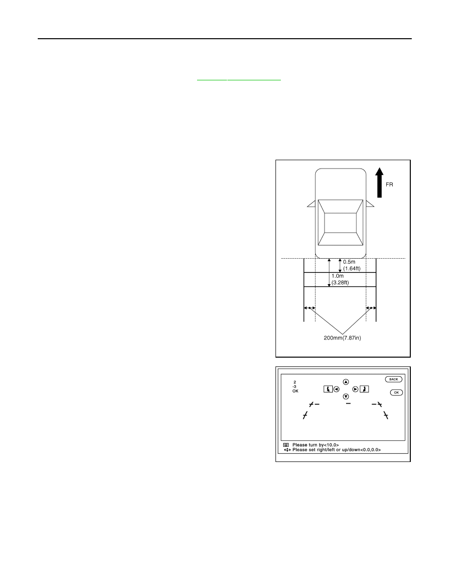
1.
Draw lines on rearward area of the vehicle passing through the
following points: 200 mm (7.87 in) from both sides of the vehicle,
and 0.5 m (1.64 ft), 1.0 m (3.28 ft) from the rear end of the
bumper.
2.
Set into “Correct Draw Line of Rear view Camera” mode of
“Confirmation/Adjustment” mode.
3.
Rotate the center dial, and then select the guiding line pattern so
that its angle is aligned with the correction line of the rear of the
vehicle.
4.
Make fine adjustment to the correction line of the rear of the
vehicle with up/down/left/right switches so that its position is
aligned with the guiding line. Press “OK” switch and record the
adjusted guiding line position to the AV control unit.
CAUTION:
Never operate other function such as pressing BACK while writing index data.
SKIB3691E
Selected pattern
: (
−
10
°
) – (+10
°
)
Up/Down adjustment range
: (
−
10
°
) – (+10
°
)
Left/Right adjustment range
: (
−
10
°
) – (+10
°
)
JSNIA2185ZZ
AV
STEERING ANGLE SENSOR
AV-467
< REMOVAL AND INSTALLATION >
[BOSE AUDIO WITH NAVIGATION]
C
D
E
F
G
H
I
J
K
L
M
B
A
O
P
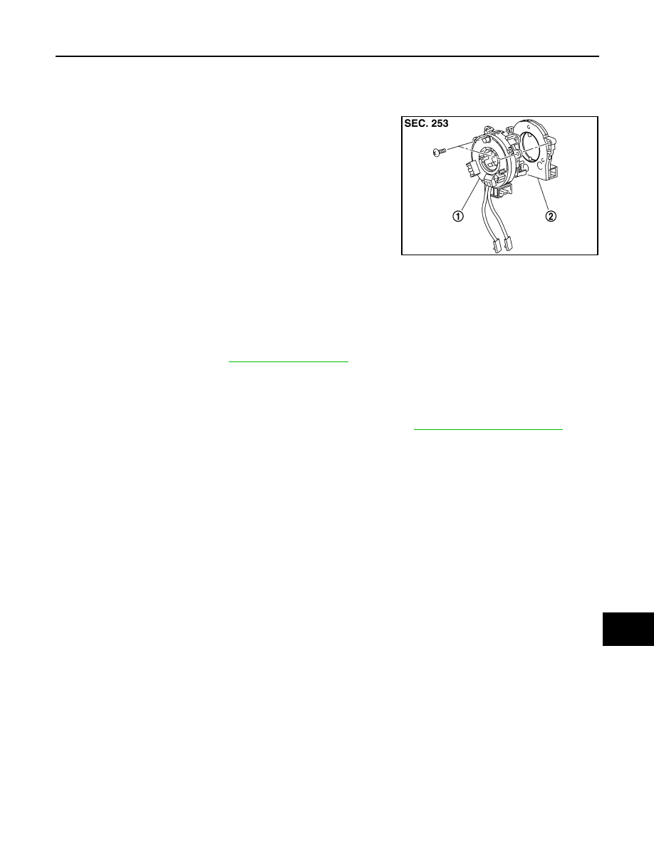
STEERING ANGLE SENSOR
Exploded View
INFOID:0000000009722007
DISASSEMBLY
Removal and Installation
INFOID:0000000009722008
REMOVAL
1.
Remove spiral cable. Refer to
.
2.
Remove steering angle sensor from spiral cable.
INSTALLATION
1.
Install in the reverse order of removal.
2.
Perform steering angle sensor neutral position adjustment. Refer to
JSNIA0135ZZ
1.
Spiral cable
2.
Steering angle sensor
AV-468
< REMOVAL AND INSTALLATION >
[BOSE AUDIO WITH NAVIGATION]
ROOF ANTENNA
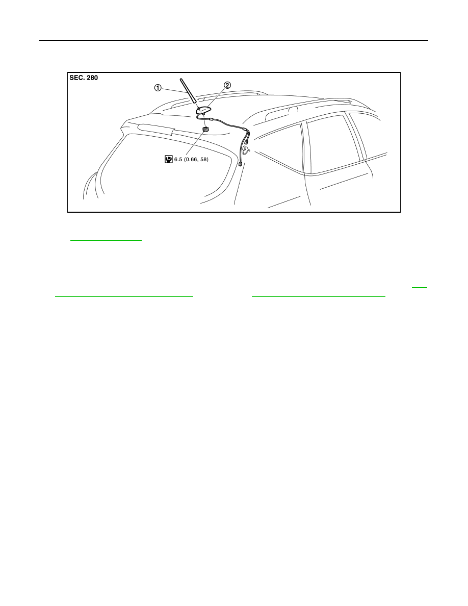
ROOF ANTENNA
Exploded View
INFOID:0000000009722009
for symbols in the figure.
Removal and Installation
INFOID:0000000009722010
REMOVAL
1.
Remove headlining assembly (rear) to secure work space between vehicle and headlining. Refer to
26, "NORMAL ROOF : Exploded View"
[normal roof] or
INT-30, "SUNROOF : Exploded View"
[sunroof].
2.
Disconnect antenna feeder connectors.
3.
Remove antenna base mounting nut, and then remove antenna base from roof panel.
INSTALLATION
Install in the reverse order of removal.
CAUTION:
If the antenna base mounting nut is tightened looser than the specified torque, then this will lower the
sensitivity of the antenna. On the other hand, if the nut is tightened tighter than the specified torque,
then this will deform the roof panel.
JPNIA0786ZZ
1.
Rod antenna
2.
Antenna base
AV
ANTENNA FEEDER
AV-469
< REMOVAL AND INSTALLATION >
[BOSE AUDIO WITH NAVIGATION]
C
D
E
F
G
H
I
J
K
L
M
B
A
O
P
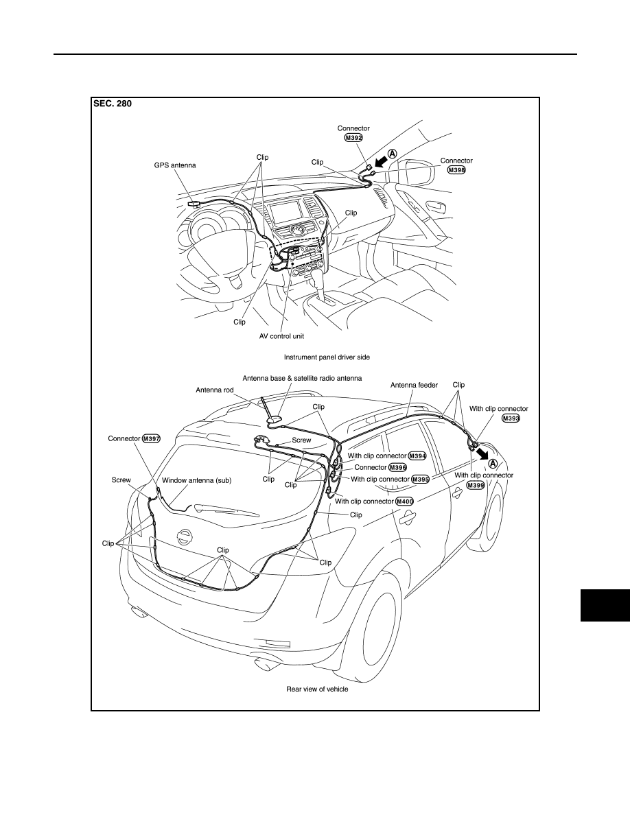
ANTENNA FEEDER
Feeder Layout
INFOID:0000000009722011
JSNIA3505GB
Нет комментариевНе стесняйтесь поделиться с нами вашим ценным мнением.
Текст