Nissan Murano. Manual — part 920
IP-16
< REMOVAL AND INSTALLATION >
INSTRUMENT PANEL ASSEMBLY
[ ]: Number indicates step in removal procedures.
WARNING:
Before servicing, turn ignition switch OFF, disconnect battery negative terminal and wait 3 minutes or
more.
CAUTION:
When removing, always use a remover tool that is made of plastic.
REMOVAL
1.
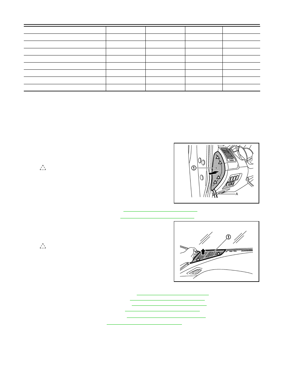
Remove instrument side finisher LH.
1.
Insert a remover tool (A) into lower space.
2.
Pull the instrument side finisher LH (1) crosswise.
2.
Remove front body side welt LH. Refer to
INT-20, "Removal and Installation"
.
3.
Remove front pillar garnish LH. Refer to
INT-20, "Removal and Installation"
4.
Remove speaker grille LH.
1.
Pull up speaker grille LH (1) to disengage pawls.
2.
Remove speaker grille LH.
5.
Remove front squawker LH. Refer to the following.
• For Base audio without color display: Refer to
AV-43, "Removal and Installation"
.
• For Base audio with color display: Refer to
AV-153, "Removal and Installation"
• For Bose audio without navigation: Refer to
AV-280, "Removal and Installation"
.
• For Bose audio with navigation: Refer to
AV-452, "Removal and Installation"
.
6.
Remove vehicle security indicator. Refer to
SEC-192, "Removal and Installation"
.
7.
Remove sunload sensor. Refer to
VTL-28, "Removal and Installation"
.
Instrument side finisher RH
[24]
Front body side welt RH
[25]
Front pillar garnish RH
[26]
Speaker grille RH
[27]
Front squawker RH
[28]
Instrument lower panel RH
[29]
Passenger air bag module harness connector
[30]
Passenger air bag module mounting bolt
[31]
Instrument panel assembly
[32]
: Pawl
JMJIA1314ZZ
: Pawl
JMJIA1315ZZ
INSTRUMENT PANEL ASSEMBLY
IP-17
< REMOVAL AND INSTALLATION >
C
D
E
F
G
H
I
K
L
M
A
B
IP
N
O
P
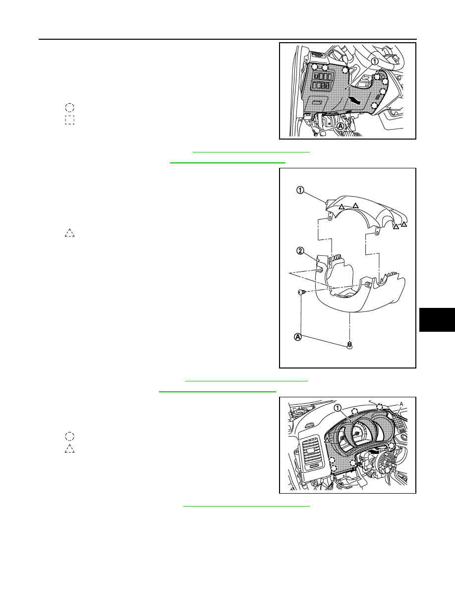
8.
Remove instrument lower panel LH.
1.
Remove hood opener lever fixing bolts (A).
2.
Pull back instrument lower panel LH (1).
3.
Release data link connector (pawl) then remove it from
instrument lower panel LH.
4.
Disconnect harness connectors and aspirator duct.
9.
Remove driver air bag module. Refer to
SR-12, "Removal and Installation"
.
10. Remove steering wheel. Refer to
ST-36, "Removal and Installation"
.
11. Remove steering column covers.
1.
Remove steering column cover fixing screws (A).
2.
Pull up steering column upper cover (1), and then remove
steering column upper cover.
3.
Pull down steering column lower cover (2), and then remove
steering column lower cover.
12. Remove combination switch. Refer to
BCS-99, "Removal and Installation"
13. Remove spiral cable. Refer to
SR-15, "Removal and Installation"
.
14. Remove cluster lid A.
1.
Pull back cluster lid A (1), and disengage clips and pawl.
2.
Remove cluster lid A.
15. Remove combination meter. Refer to
MWI-105, "Removal and Installation"
.
: Clip
: Metal clip
JMJIA1316ZZ
: Pawl
JMJIA1317ZZ
: Clip
: Pawl
JMJIA1318ZZ
IP-18
< REMOVAL AND INSTALLATION >
INSTRUMENT PANEL ASSEMBLY
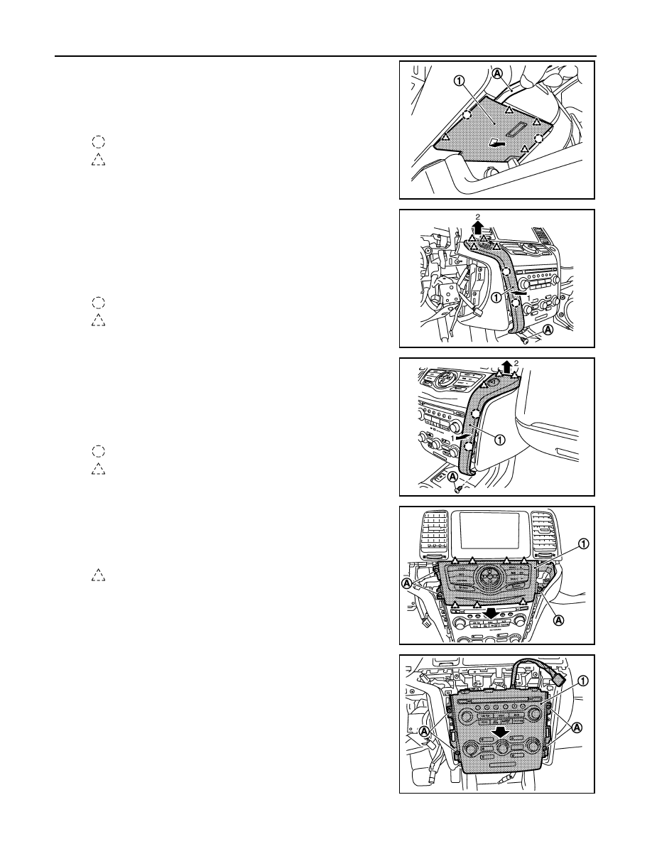
16. Remove cluster lid C (lower).
1.
Disengage cluster lid C (lower) (1) fixing clips and pawls
with remover tool (A).
2.
Pull down cluster lid C (lower).
3.
Disconnect illumination lamp harness connector.
17. Remove instrument stay cover LH.
1.
Remove instrument stay cover LH (1) fixing screw (A).
2.
Disengage instrument stay cover LH fixing clips and pawls
with remover tool.
3.
Pull back and pull up instrument stay cover LH.
4.
Disconnect push button ignition switch harness connector
18. Remove instrument stay cover RH.
1.
Remove instrument stay cover RH (1) fixing screw (A).
2.
Disengage instrument stay cover RH fixing clips and pawls
with remover tool.
3.
Pull back and pull up instrument stay cover RH.
4.
Disconnect hazard switch harness connector.
19. Remove cluster lid D.
1.
Remove cluster lid D (1) fixing screws (A).
2.
Pull back cluster lid D.
3.
Disconnect harness connector.
20. Remove cluster lid C.
1.
Remove cluster lid C (1) fixing screws (A).
2.
Pull back cluster lid C.
3.
Disconnect harness connectors.
: Clip
: Pawl
JMJIA1319ZZ
: Clip
: Pawl
JMJIA1320ZZ
: Clip
: Pawl
JMJIA1321ZZ
: Pawl
JMJIA1322ZZ
JMJIA1323ZZ
INSTRUMENT PANEL ASSEMBLY
IP-19
< REMOVAL AND INSTALLATION >
C
D
E
F
G
H
I
K
L
M
A
B
IP
N
O
P
21. Remove AV control unit or audio unit.
• AV control unit: Refer to the following.
For Base audio with color display: Refer to
AV-149, "Removal and Installation"
For Bose audio without navigation: Refer to
AV-276, "Removal and Installation"
.
For Bose audio with navigation: Refer to
AV-448, "Removal and Installation"
.
• Audio unit: Refer to
AV-39, "Removal and Installation"
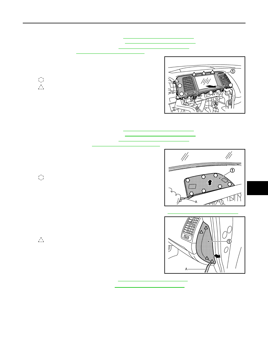
22. Remove center ventilator assembly.
1.
Remove center ventilator assembly (1) fixing screws (A).
2.
Pull back center ventilator assembly.
23. Remove display unit or audio display unit.
• Display unit: Refer to the following.
For Base audio with color display: Refer to
AV-150, "Removal and Installation"
For Bose audio without navigation: Refer to
AV-277, "Removal and Installation"
.
For Bose audio with navigation: Refer to
AV-449, "Removal and Installation"
.
• Audio display unit: Refer to
AV-40, "Removal and Installation"
24. Remove center speaker grille.
1.
Disengage center speaker grille (1) fixing clips with remover
tool (A).
2.
Pull up center speaker grille.
25. Remove center speaker (BOSE audio with NAVI models). Refer to
AV-454, "Removal and Installation"
26. Remove instrument side finisher RH.
1.
Insert a remover tool (A) into lower space.
2.
Pull the instrument side finisher RH (1) crosswise.
27. Remove front body side welt RH. Refer to
INT-20, "Removal and Installation"
28. Remove front pillar garnish RH. Refer to
INT-20, "Removal and Installation"
.
: Clip
: Pawl
JMJIA1325ZZ
: Clip
JMJIA1327ZZ
: Pawl
JMJIA1328ZZ
Нет комментариевНе стесняйтесь поделиться с нами вашим ценным мнением.
Текст