Nissan Murano. Manual — part 553
EC-322
< DTC/CIRCUIT DIAGNOSIS >
[VQ35DE]
P0453 EVAP CONTROL SYSTEM PRESSURE SENSOR
17.
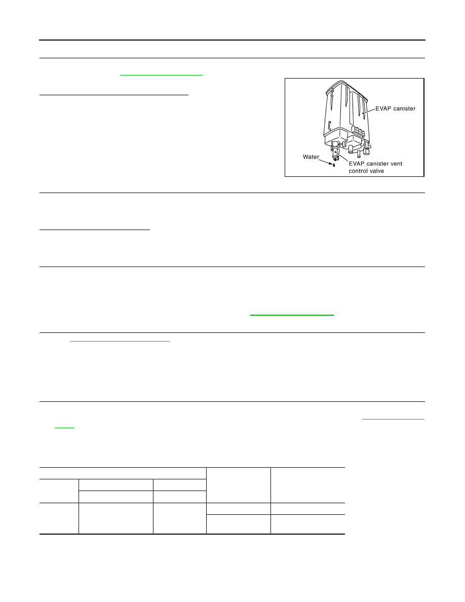
CHECK IF EVAP CANISTER IS SATURATED WITH WATER
1.
Remove EVAP canister with EVAP canister vent control valve and EVAP control system pressure sensor
attached. Refer to
.
2.
Check if water will drain from the EVAP canister.
Does water drain from the EVAP canister?
YES
>> GO TO 18.
NO
>> GO TO 20.
18.
CHECK EVAP CANISTER
Weigh the EVAP canister with the EVAP canister vent control valve and EVAP control system pressure sensor
attached.
The weight should be less than 2.1 kg (4.6 lb).
Is the inspection result normal?
YES
>> GO TO 20.
NO
>> GO TO 19.
19.
DETECT MALFUNCTIONING PART
Check the following.
• EVAP canister for damage
• EVAP hose between EVAP canister and vehicle frame for clogging or poor connection
>> Repair hose or replace EVAP canister. Refer to
20.
CHECK INTERMITTENT INCIDENT
GI-44, "Intermittent Incident"
>> INSPECTION END
Component Inspection
INFOID:0000000009720047
1.
CHECK EVAP CONTROL SYSTEM PRESSURE SENSOR
1.
Turn ignition switch OFF.
2.
Remove EVAP control system pressure sensor with its harness connector. Refer to
.
Always replace O-ring with a new one.
3.
Install a vacuum pump to EVAP control system pressure sensor.
4.
Turn ignition switch ON and check output voltage between ECM terminals under the following conditions.
CAUTION:
• Always calibrate the vacuum pump gauge when using it.
• Never apply below -93.3 kPa (-0.952 kg/cm
2
, -13.53 psi) or pressure over 101.3 kPa (1.033 kg/cm
2
,
14.69 psi).
JMBIA1134GB
ECM
Applied vacuum kPa
(kg/cm
2
, psi)
Voltage
Connector
+
–
Terminal
Terminal
E16
86
(EVAP control system
pressure sensor signal)
96
(Sensor ground)
Not applied
1.8 - 4.8 V
-26.7 (-0.272, -3.87)
2.1 to 2.5 V lower than
above value
P0453 EVAP CONTROL SYSTEM PRESSURE SENSOR
EC-323
< DTC/CIRCUIT DIAGNOSIS >
[VQ35DE]
C
D
E
F
G
H
I
J
K
L
M
A
EC
N
P
O
Is the inspection result normal?
YES
>> INSPECTION END
NO
>> Replace EVAP control system pressure sensor. Refer to
EC-324
< DTC/CIRCUIT DIAGNOSIS >
[VQ35DE]
P0456 EVAP CONTROL SYSTEM
P0456 EVAP CONTROL SYSTEM
DTC Logic
INFOID:0000000009720048
DTC DETECTION LOGIC
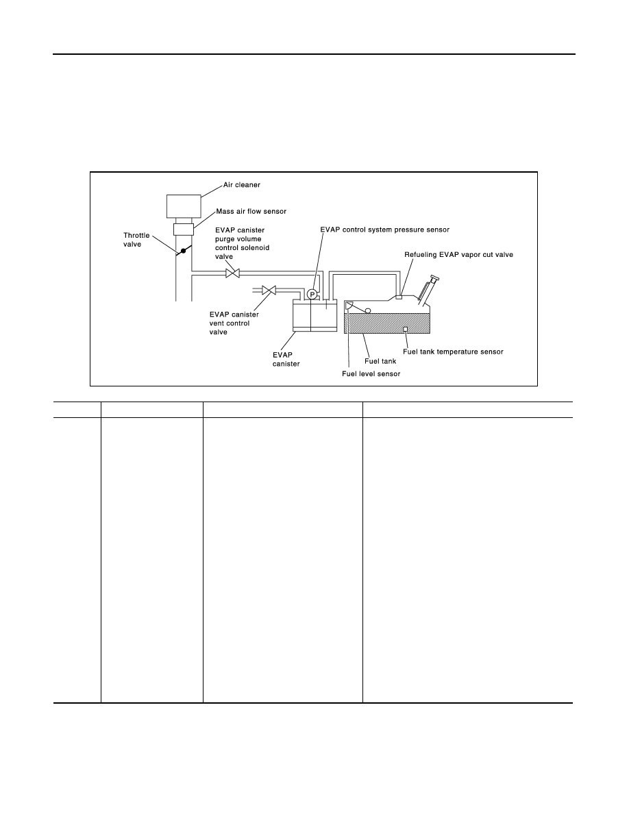
This diagnosis detects leaks in the EVAP line between fuel tank and EVAP canister purge volume control sole-
noid valve, using the negative pressure caused by decrease of fuel temperature in the fuel tank after turning
ignition switch OFF.
If ECM judges there are no leaks, the diagnosis will be OK.
CAUTION:
• Use only a genuine NISSAN fuel filler cap as a replacement. If an incorrect fuel filler cap is used, the
MIL may illuminate.
• If the fuel filler cap is not tightened properly, the MIL may illuminate.
• Use only a genuine NISSAN rubber tube as a replacement.
DTC CONFIRMATION PROCEDURE
DTC No.
Trouble diagnosis name
DTC detecting condition
Possible cause
P0456
Evaporative emission
control system leak
• EVAP system has a leak.
• EVAP system does not operate prop-
erly.
• Incorrect fuel tank vacuum relief valve
• Incorrect fuel filler cap used
• Fuel filler cap remains open or does not close.
• Foreign matter caught in fuel filler cap.
• Leakage is in line between intake manifold and
EVAP canister purge volume control solenoid
valve.
• Foreign matter caught in EVAP canister vent con-
trol valve.
• EVAP canister or fuel tank leakage
• EVAP purge line (pipe and rubber tube) leakage
• EVAP purge line rubber tube bent
• Loose or disconnected rubber tube
• EVAP canister vent control valve and the circuit
• EVAP canister purge volume control solenoid
valve and the circuit
• Fuel tank temperature sensor
• O-ring of EVAP canister vent control valve is miss-
ing or damaged
• EVAP canister is saturated with water
• EVAP control system pressure sensor
• Refueling EVAP vapor cut valve
• ORVR system leakage
• Fuel level sensor and the circuit
• Foreign matter caught in EVAP canister purge vol-
ume control solenoid valve
PBIB1026E
P0456 EVAP CONTROL SYSTEM
EC-325
< DTC/CIRCUIT DIAGNOSIS >
[VQ35DE]
C
D
E
F
G
H
I
J
K
L
M
A
EC
N
P
O
1.
PRECONDITIONING
If DTC Confirmation Procedure has been previously conducted, always perform the following before conduct-
ing the next test.
1.
Turn ignition switch OFF and wait at least 10 seconds.
2.
Turn ignition switch ON.
3.
Turn ignition switch OFF and wait at least 10 seconds.
Do you have CONSULT?
YES
>> GO TO 2.
NO
>> GO TO 4.
2.
PERFORM DTC CONFIRMATION PROCEDURE-I
WITH CONSULT
1.
Turn ignition switch ON and select “EVAP DIAG READY” in “DATA MONITOR” mode with CONSULT.
2.
Start engine and wait at idle until “OFF” of “EVAP DIAG READY” changes to “ON”.
NOTE:
It will take at most 2 hours until “OFF” of “EVAP DIAG READY” changes to “ON”.
3.
Turn ignition switch OFF and wait at least 90 minutes.
NOTE:
Never turn ignition switch ON during 90 minutes.
4.
Turn ignition switch ON and select “EVAP LEAK DIAG” in “DATA MONITOR” mode with CONSULT.
5.
Check that “EVAP LEAK DIAG” indication.
Which is displayed on CONSULT?
CMPLT >> GO TO 3.
YET
>> Perform DTC CONFIRMATION PROCEDURE again. GO TO 1.
3.
PERFORM DTC CONFIRMATION PROCEDURE-II
Check 1st trip DTC.
Is 1st trip DTC detected?
YES
>> Proceed to
.
NO
>> INSPECTION END.
4.
PERFORM DTC CONFIRMATION PROCEDURE
WITH GST
1.
Start engine and wait engine idle for at least 2 hours.
2.
Turn ignition switch OFF and wait at least 90 minutes.
NOTE:
Never turn ignition switch ON during 90 minutes.
3.
Turn ignition switch ON.
4.
Check 1st trip DTC.
Is 1st trip DTC detected?
YES
>> Proceed to
.
NO
>> INSPECTION END.
Diagnosis Procedure
INFOID:0000000009720049
1.
CHECK FUEL FILLER CAP DESIGN
1.
Turn ignition switch OFF.
Нет комментариевНе стесняйтесь поделиться с нами вашим ценным мнением.
Текст