Nissan Murano. Manual — part 255
BODY ALIGNMENT
BRM-45
< SERVICE DATA AND SPECIFICATIONS (SDS)
[FOR USA AND CANADA]
C
D
E
F
G
H
I
J
L
M
A
B
BRM
N
O
P
Description
INFOID:0000000009718058
• All dimensions indicated in the figures are actual.
• When using a tracking gauge, adjust both pointers to equal length. Then check the pointers and gauge itself
to make sure there is no free play.
• When a measuring tape is used, check to be sure there is no elongation, twisting or bending.
• Measurements should be taken at the center of the mounting holes.
• An asterisk (*) following the value at the measuring point indicates that the measuring point on the other side
is symmetrically the same value.
• The coordinates of the measurement points are the distances measured from the standard line of
″
X
″
,
″
Y
″
and
″
Z
″
.
•
″
Z
″
: Imaginary base line [200 mm (7.87 in) below datum line (
″
0Z
″
at design plan)]
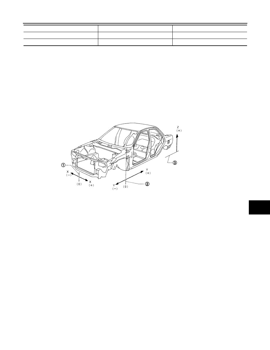
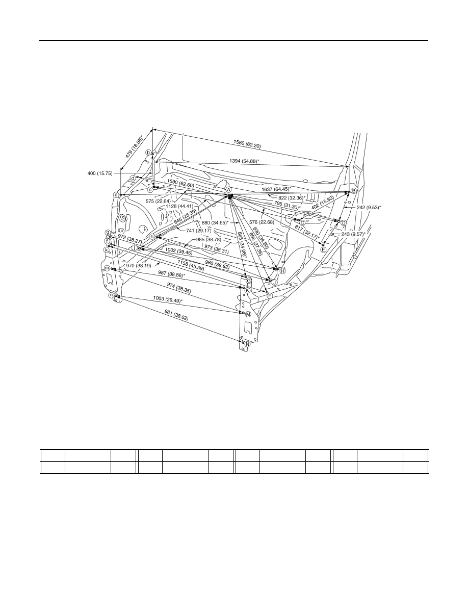
Engine Compartment
INFOID:0000000009718059
MEASUREMENT
Dimensions marked with
″
*
″
indicate symmetrically identical dimensions on both the right and left hand of the
vehicle.
E
Front floor reinforcement
Hole
φ
9 (0.35)
F
Front floor
Embossment
Points
Portion
Marks
1.
Vehicle center
2.
Front axle center
3.
Imaginary base line
JSKIA0073GB
BRM-46
< SERVICE DATA AND SPECIFICATIONS (SDS)
[FOR USA AND CANADA]
BODY ALIGNMENT
«The others»
Unit: mm (in)
MEASUREMENT POINTS
Unit: mm (in)
JSKIA0544GB
Point
Dimension
Memo
Point
Dimension
Memo
Point
Dimension
Memo
Point
Dimension
Memo
B - c
1394 (54.88)*
E - e
1550 (61.02)
BODY ALIGNMENT
BRM-47
< SERVICE DATA AND SPECIFICATIONS (SDS)
[FOR USA AND CANADA]
C
D
E
F
G
H
I
J
L
M
A
B
BRM
N
O
P
Unit: mm (in)
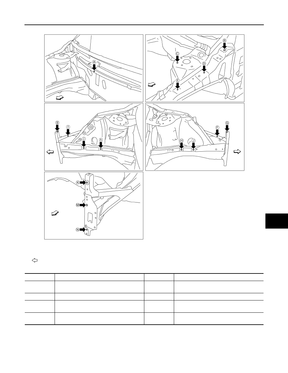
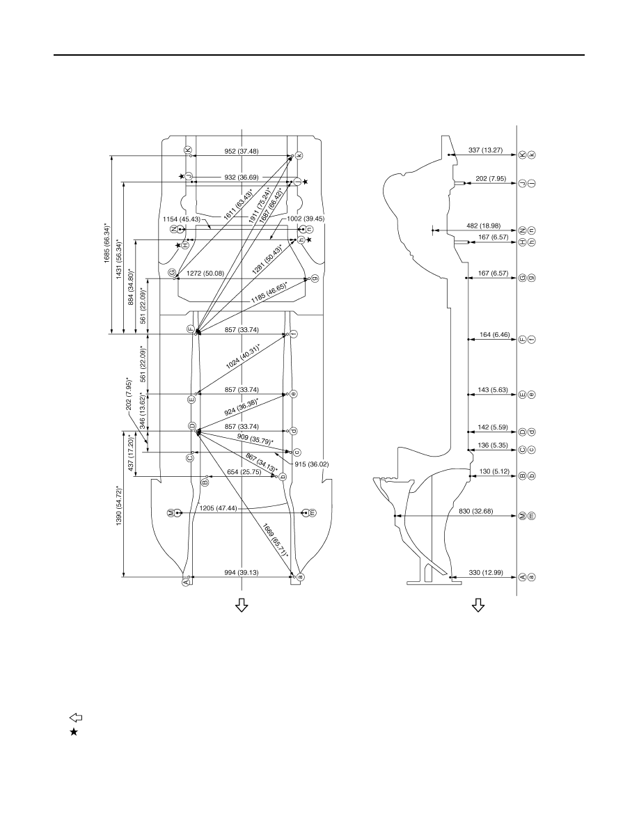
Underbody
INFOID:0000000009718060
MEASUREMENT
Dimensions marked with
″
*
″
indicate symmetrically identical dimensions on both the right and left hand of the
vehicle.
: Vehicle front
JSKIA0545ZZ
Point
Material
Point
Material
A
Cowl top extension installing hole center of cen-
ter positioning mark
φ
7 (0.28)
F, f
Upper radiator core support hole center
φ
12
(0.47)
B, b
Hood hinge installing hole center
φ
13 (0.51)
G, g, K, k, N, n
Front end module installing hole center
φ
9 (0.35)
C, c
Front strut installing hole center 16
×
10
(0.63
×
0.39)
H, h, J, j
Front side member hole center
φ
14 (0.55)
D, d, E, e
Upper front fender bracket installing hole center
φ
7 (0.28)
M, m
Bumper stay installing hole center
φ
12 (0.47)
BRM-48
< SERVICE DATA AND SPECIFICATIONS (SDS)
[FOR USA AND CANADA]
BODY ALIGNMENT
MEASUREMENT POINTS
Unit: mm (in)
: Vehicle front
: Bolt head
JSKIA0790GB
Нет комментариевНе стесняйтесь поделиться с нами вашим ценным мнением.
Текст