Nissan Murano. Manual — part 162
AV-426
< DTC/CIRCUIT DIAGNOSIS >
[BOSE AUDIO WITH NAVIGATION]
CAMERA IMAGE SIGNAL CIRCUIT
Is inspection result normal?
YES
>> Replace display unit. Refer to
.
NO
>> Replace rear view camera. Refer to
AV-465, "Exploded View (Models without BSW and LDW)"
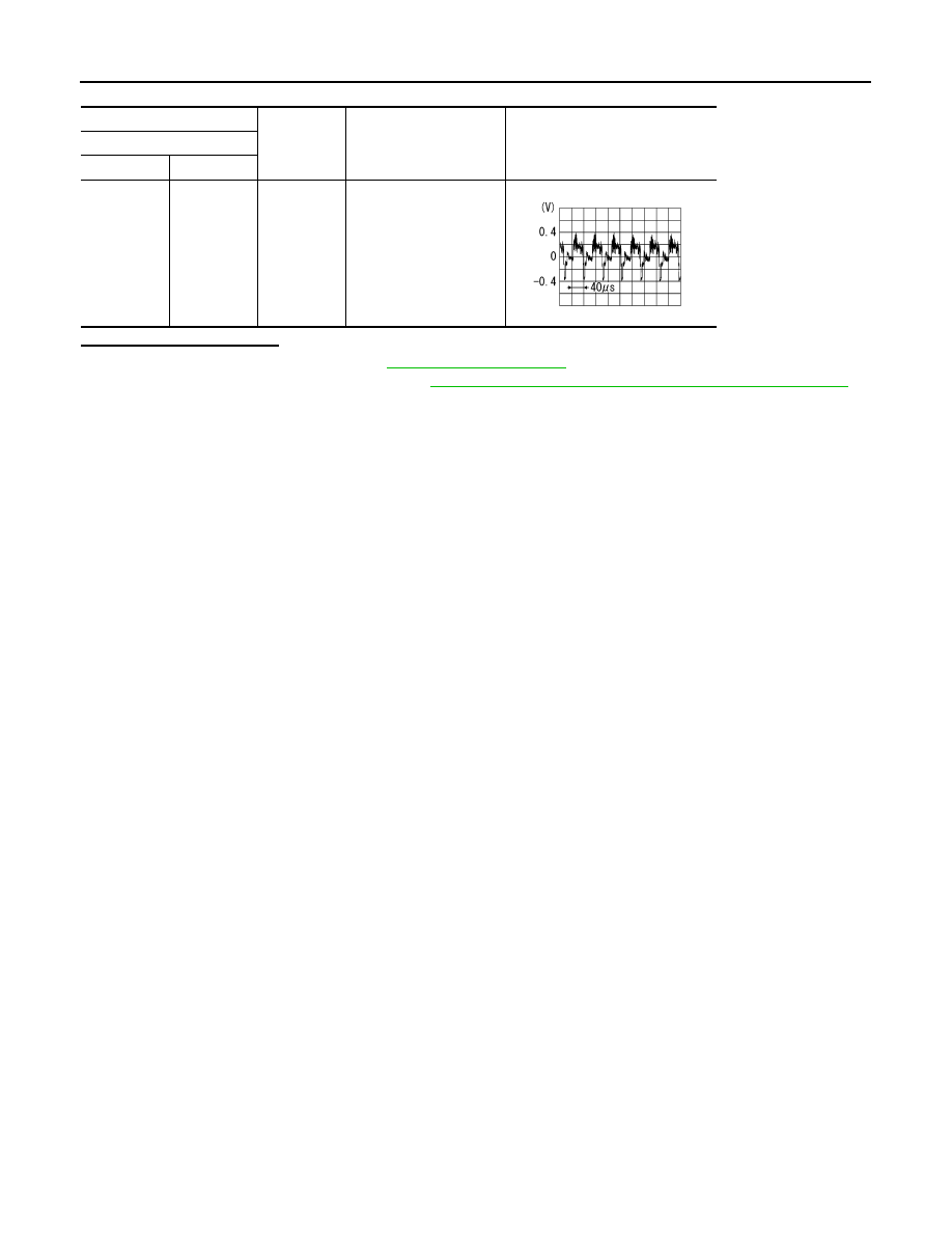
(+)
(
−
)
Condition
Reference value
Display unit
Connector
Terminal
M195
8
Ground
At camera image is dis-
played.
SKIB2251J
AV
DISK EJECT SIGNAL CIRCUIT
AV-427
< DTC/CIRCUIT DIAGNOSIS >
[BOSE AUDIO WITH NAVIGATION]
C
D
E
F
G
H
I
J
K
L
M
B
A
O
P
DISK EJECT SIGNAL CIRCUIT
Description
INFOID:0000000009721956
The eject signal is output to AV control unit when the eject switch of multifunction switch is pressed.
Diagnosis Procedure
INFOID:0000000009721957
1.
CHECK CONTINUITY DISK EJECT SIGNAL CIRCUIT
1.
Turn ignition switch OFF.
2.
Disconnect multifunction switch connector and AV control unit connector.
3.
Check continuity between multifunction switch harness connector and AV control unit harness connector.
4.
Check continuity between multifunction switch harness connector and ground.
Is the inspection result normal?
YES
>> GO TO 2.
NO
>> Repair harness or connector.
2.
CHECK AV CONTROL UNIT VOLTAGE
1.
Connect multifunction switch connector and AV control unit connector.
2.
Turn ignition switch ON.
3.
Check voltage between AV control unit harness connector and ground.
Is the inspection result normal?
YES
>> Replace preset switch. Refer to
NO
>> Replace AV control unit. Refer to
Multifunction switch
AV control unit
Continuity
Connector
Terminal
Connector
Terminal
M125
14
M179
29
Existed
Multifunction switch
Ground
Continuity
Connector
Terminal
M125
14
Not existed
(+)
(
−
)
Condition
Voltage
(Approx.)
AV control unit
Connector
Terminal
M179
29
Ground
Pressing the eject switch
0 V
Except for above
5.0 V
AV-428
< DTC/CIRCUIT DIAGNOSIS >
[BOSE AUDIO WITH NAVIGATION]
MICROPHONE SIGNAL CIRCUIT
MICROPHONE SIGNAL CIRCUIT
Description
INFOID:0000000009721958
Supply power from AV control unit to microphone. The microphone transmits the sound/voice to the AV control
unit.
Diagnosis Procedure
INFOID:0000000009721959
1.
CHECK CONTINUITY BETWEEN AV CONTROL UNIT AND MICROPHONE CIRCUIT
1.
Turn ignition switch OFF.
2.
Disconnect AV control unit connector and microphone connector.
3.
Check continuity between AV control unit harness connector and microphone harness connector.
4.
Check continuity between AV control unit harness connector and ground.
Is the inspection result normal?
YES
>> GO TO 2.
NO
>> Repair harness or connector.
2.
CHECK VOLTAGE MICROPHONE VCC
1.
Connect AV control unit connector.
2.
Turn ignition switch ON.
3.
Check voltage between AV control unit harness connector.
Is the inspection result normal?
YES
>> GO TO 3.
NO
>> Replace AV control unit. Refer to
3.
CHECK MICROPHONE SIGNAL
1.
Connect microphone connector.
2.
Check signal between AV control unit harness connector.
AV control unit
Microphone
Continuity
Connector
Terminals
Connector
Terminals
M180
71
R20
2
Existed
72
4
87
1
AV control unit
Ground
Continuity
Connector
Terminals
M180
72
Not existed
87
(+)
(
−
)
Voltage
(Approx.)
AV control unit
Ground
Connector
Terminal
M180
72
5.0 V
AV
MICROPHONE SIGNAL CIRCUIT
AV-429
< DTC/CIRCUIT DIAGNOSIS >
[BOSE AUDIO WITH NAVIGATION]
C
D
E
F
G
H
I
J
K
L
M
B
A
O
P
Is the inspection result normal?
YES
>> Replace AV control unit. Refer to
NO
>> Replace microphone. Refer to
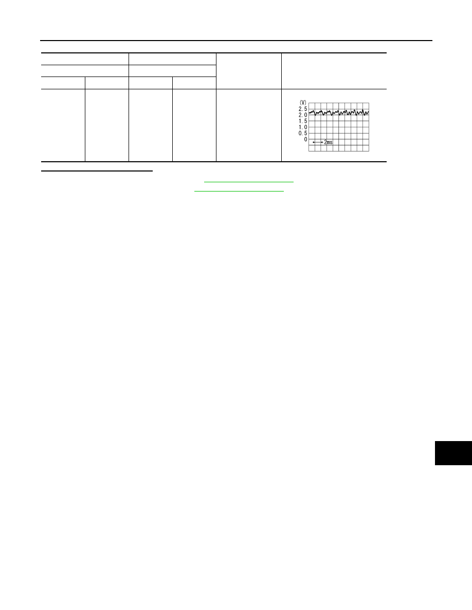
(+)
(
−
)
Condition
Reference value
AV control unit
AV control unit
Connector
Terminal
Connector
Terminal
M180
87
M180
71
Give a voice.
PKIB5037J
Нет комментариевНе стесняйтесь поделиться с нами вашим ценным мнением.
Текст