Nissan Murano. Manual — part 618
EM-46
< REMOVAL AND INSTALLATION >
OIL PAN AND OIL STRAINER
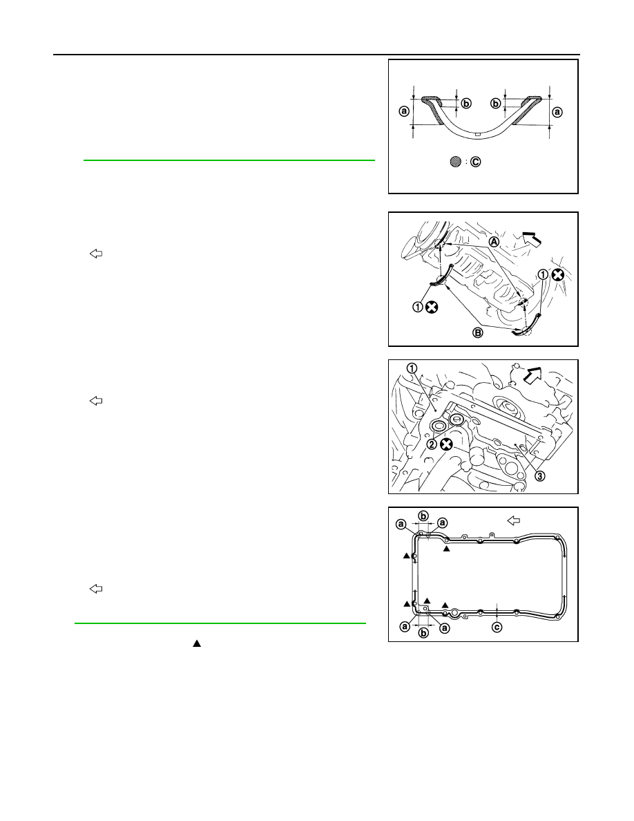
• Apply liquid gasket to new oil pan gaskets as shown in the fig-
ure.
Use Genuine RTV Silicone Sealant or equivalent. Refer to
GI-22, "Recommended Chemical Products and Sealants"
.
• To install, align protrusion (B) of oil pan gasket with notches
(A) of front timing chain case and rear oil seal retainer.
• Install oil pan gasket (1) with smaller arc to front timing chain
case side.
c.
Install new O-rings (2) on the bottom of cylinder block (1) and oil
pump (3).
CAUTION:
Do not reuse O-rings.
d.
Apply a continuous bead of liquid gasket with the tube presser
(commercial service tool) to the cylinder block mating surface of
oil pan (upper) to a limited portion as shown in the figure.
Use Genuine RTV Silicone Sealant or equivalent. Refer to
GI-22, "Recommended Chemical Products and Sealants"
.
CAUTION:
• For bolt holes with marks (5 locations), apply liquid
gasket outside the holes.
• Apply a bead of 4.5 to 5.5 mm (0.177 to 0.217 in) diameter to area (a).
• Attaching should be done within 5 minutes after coating.
e.
Install oil pan (upper).
CAUTION:
Install avoiding misalignment of both O-rings.
C
: Sealing point
a
: 15 mm (0.59 in)
b
: 5 mm (0.20 in)
JPBIA0432ZZ
: Engine front
JPBIA0433ZZ
: Engine front
JPBIA1379ZZ
b
: 35 mm (1.38 in)
c
:
φ
3.5 - 4.5 mm (0.138 - 0.177 in)
: Engine front
JPBIA0434ZZ
OIL PAN AND OIL STRAINER
EM-47
< REMOVAL AND INSTALLATION >
C
D
E
F
G
H
I
J
K
L
M
A
EM
N
P
O
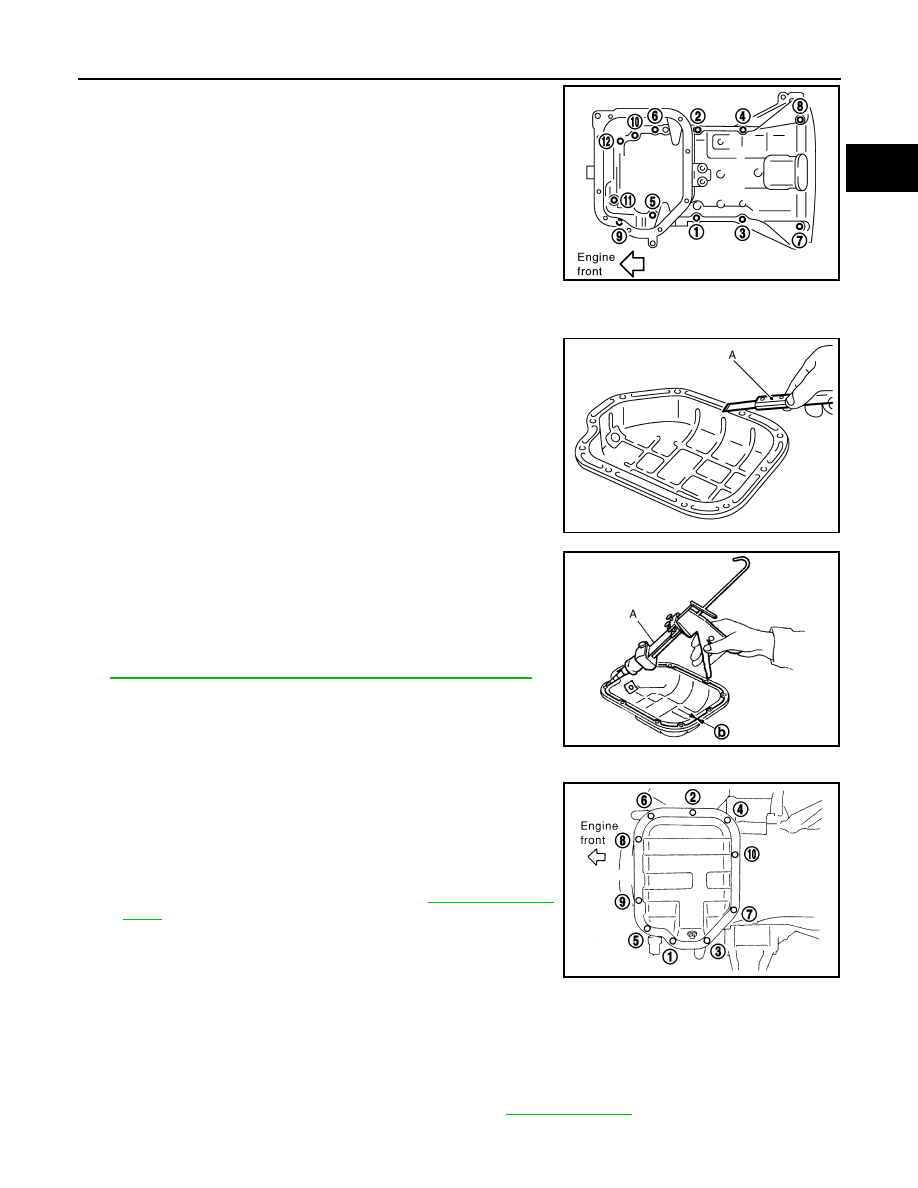
• Tighten mounting bolts in numerical order as shown in the fig-
ure.
• There are three types of mounting bolts. Refer to the following
for locating bolts.
2.
Install oil strainer to oil pump.
3.
Install oil pan (lower) as follows:
a.
Use scraper (A) to remove old liquid gasket from mating sur-
faces.
• Remove old liquid gasket from the bolt holes and thread.
CAUTION:
Never scratch or damage the mating surfaces when clean-
ing off old liquid gasket.
b.
Apply a continuous bead of liquid gasket with the tube presser
(commercial service tool) (A) to the oil pan (lower) as shown in
the figure.
Use Genuine RTV Silicone Sealant or equivalent. Refer to
GI-22, "Recommended Chemical Products and Sealants"
.
CAUTION:
Attaching should be done within 5 minutes after coating.
c.
Install oil pan (lower).
• Tighten mounting bolts in numerical order as shown in the fig-
ure.
4.
Install oil pan drain plug.
CAUTION:
Do not reuse drain plug washer.
• Refer to the figure of components of former page for installa-
tion direction of drain plug washer. Refer to
.
5.
Install in the reverse order of removal after this step.
NOTE:
At least 30 minutes after oil pan is installed, pour engine oil.
Inspection
INFOID:0000000009717976
INSPECTION AFTER REMOVAL
Clean oil strainer if any object attached.
INSPECTION AFTER INSTALLATION
1.
Check the engine oil level and adjust engine oil. Refer to
2.
Start engine, and check there is no leakage of engine oil.
M8
×
135 mm (5.31 in)
: 11
M8
×
92 mm (3.62 in)
: 5, 7, 8
M8
×
25 mm (0.98 in)
: Except the above
PBIC1636E
JPBIA0025ZZ
b
:
φ
4.0 - 5.0 mm (0.157 - 0.197 in)
JPBIA0026ZZ
PBIC0782E
EM-48
< REMOVAL AND INSTALLATION >
OIL PAN AND OIL STRAINER
3.
Stop engine and wait for 10 minutes.
4.
Check the engine oil level again. Refer to
.

FUEL INJECTOR AND FUEL TUBE
EM-49
< REMOVAL AND INSTALLATION >
C
D
E
F
G
H
I
J
K
L
M
A
EM
N
P
O
FUEL INJECTOR AND FUEL TUBE
Exploded View
INFOID:0000000009717977
CAUTION:
Never remove or disassemble parts unless instructed as shown in the figure.
Removal and Installation
INFOID:0000000009717978
REMOVAL
WARNING:
• Put a “CAUTION: FLAMMABLE” sign in the workshop.
• Be sure to work in a well ventilated area and furnish workshop with a CO
2
fire extinguisher.
• Never smoke while servicing fuel system. Keep open flames and sparks away from the work area.
• To avoid the danger of being scalded, never drain engine coolant when engine is hot.
1.
Fuel feed hose
2.
Quick connector cap
3.
Fuel tube
4.
O-ring
5.
Fuel damper
6.
Fuel damper cap
7.
Clip
8.
O-ring (black)
9.
Fuel injector
10. O-ring (green)
A.
Comply with the assembly procedure
when tightening. Refer to
: Always replace after every disassembly.
: N·m (kg-m, ft-lb)
: N·m (kg-m, in-lb)
: Should be lubricated with oil.
JPBIA2526GB
Нет комментариевНе стесняйтесь поделиться с нами вашим ценным мнением.
Текст