Nissan Murano. Manual — part 10
ADP-32
< SYSTEM DESCRIPTION >
AUTOMATIC DRIVE POSITIONER SYSTEM
ENTRY ASSIST FUNCTION : System Diagram
INFOID:0000000009720646
ENTRY ASSIST FUNCTION : System Description
INFOID:0000000009720647
OUTLINE
The seat is in the exiting position when following condition is satisfied, the seat returns from exiting position to
the previous driving position.
NOTE:
• This function is set to OFF before delivery (initial setting).
• Further information for the system setting procedure. Refer to
ADP-9, "SYSTEM INITIALIZATION : Descrip-
OPERATION PROCEDURE
1.
Turn the ignition switch ACC.
2.
Driver seat and steering column will return from the exiting position to entry position.
OPERATION CONDITION
Satisfy all of the following items. The entry assist function is not performed if these items are not satisfied.
DETAIL FLOW
JMJIA1462GB
Item
Request status
Seat, steering column
The vehicle is not moved after performing the
exit assist function.
Switch inputs
• Power seat switch
• Tilt & telescopic switch
• Door mirror control switch
• Set switch
• Memory switch
OFF
(Not operated)
AUTOMATIC DRIVE POSITIONER SYSTEM
ADP-33
< SYSTEM DESCRIPTION >
C
D
E
F
G
H
I
K
L
M
A
B
ADP
N
O
P
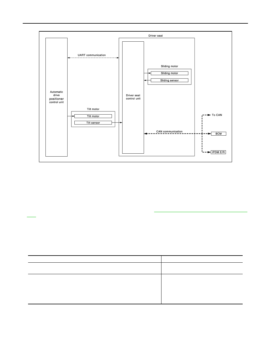
Order
Input
Output
Control unit condition
1
Ignition switch
—
Driver seat control unit receives the signals of [ignition switch signal]
from BCM via CAN communication.
2
—
Motors
(Sliding, tilt)
Driver side control unit operates the sliding motor when the operating
conditions are satisfied and requests the operations of tilt motor to
automatic drive positioner control unit via UART communication. The
automatic drive positioner operates each motor.
Sensors
(Sliding, tilt)
—
Each sensor monitors the operating positions of seat and steering,
and then stops the operation of each motor when each part reaches
the recorded address.
ADP-34
< SYSTEM DESCRIPTION >
AUTOMATIC DRIVE POSITIONER SYSTEM
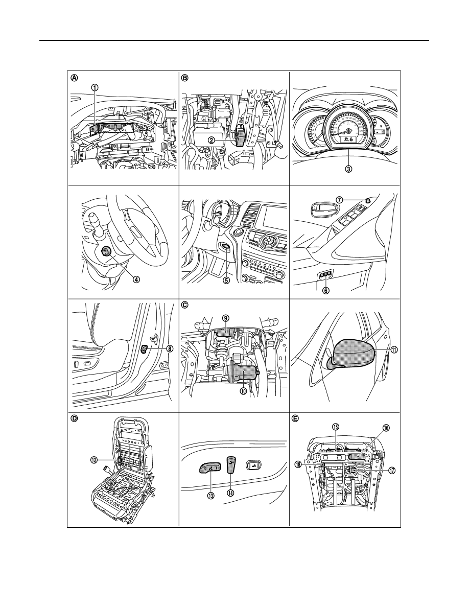
ENTRY ASSIST FUNCTION : Component Parts Location
INFOID:0000000009720648
1.
BCM M118, M119, M122, M123
2.
Automatic drive positioner control unit
M75, M104
3.
Combination meter
4.
Tilt & telescopic switch M102
5.
Key slot M99
6.
Seat memory switch D13
7.
Door mirror remote control switch
D14
8.
Front door switch (driver side) B34
9.
Tilt motor M116
JMJIA1409ZZ

AUTOMATIC DRIVE POSITIONER SYSTEM
ADP-35
< SYSTEM DESCRIPTION >
C
D
E
F
G
H
I
K
L
M
A
B
ADP
N
O
P
ENTRY ASSIST FUNCTION : Component Description
INFOID:0000000009720649
CONTROL UNITS
INPUT PARTS
Switches
10. Telescopic motor M117
11.
Door mirror (driver side) D3
12. Reclining motor B461
13. Sliding, Lifting switch
(Power seat switch B459)
14. Reclining switch
(Power seat switch B459)
15. Driver seat control unit B451,B452
16. Sliding motor B461
17. Lifting motor (front) B455
18. Lifting motor (rear) B456
A.
Behind the combination meter
B.
View with instrument driver lower
panel removed
C.
View with instrument driver lower
panel removed
D.
View with seat cushion and seatback
pad removed
E.
Backside of the seat cushion
Item
Function
Driver seat control unit
• Main units of automatic drive positioner system
• It is connected to the CAN.
• It communicates with the automatic drive positioner control via UART communi-
cation.
Automatic drive positioner control unit
• It communicates with the driver seat control unit via UART communication.
• Perform various controls with the instructions of driver seat control unit.
• Perform the controls of the tilt & telescopic, door mirror switch.
BCM
Transmit the following status to the driver seat control unit via CAN communication.
• Driver door: OPEN/CLOSE
• Ignition switch position: ACC/ON
• Door lock: UNLOCK (with Intelligent Key or driver side door request switch oper-
ation)
• Key ID
• Key switch: Insert/Pull out Intelligent Key
• Starter: CRANKING/OTHER
• Handle position : LHD
Combination meter / ABS
Transmit the vehicle speed signal to the driver seat control unit via CAN communi-
cation.
TCM
Transmit the shift position signal (P range) to the driver seat control unit via CAN
communication.
Item
Function
Key slot
The key switch is installed to detect the key inserted/removed status.
Front door switch (driver side)
Detect front door (driver side) open/close status.
CVT shift selector (detention switch)
Detect the P range position of selector lever.
Set switch
The registration and system setting can be performed with its operation.
Memory switch 1/2
The registration and operation can be performed with its operation.
Power seat switch
The following switch is installed.
• Reclining switch
• Lifting switch (front)
• Lifting switch (rear)
• Sliding switch
The specific parts can be operated with the operation of each switch.
Нет комментариевНе стесняйтесь поделиться с нами вашим ценным мнением.
Текст