Nissan Murano. Manual — part 491
EC-74
< SYSTEM DESCRIPTION >
[VQ35DE]
COOLING FAN CONTROL
COOLING FAN CONTROL
System Diagram
INFOID:0000000009719843
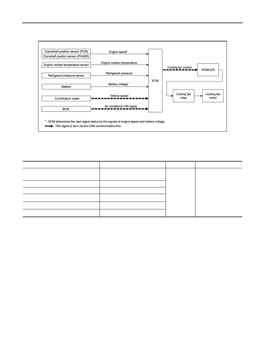
System Description
INFOID:0000000009719844
INPUT/OUTPUT SIGNAL CHART
*1: The ECM determines the start signal status by the signals of engine speed and battery voltage.
*2: This signal is sent to ECM via the CAN communication line.
SYSTEM DESCRIPTION
The ECM controls the cooling fan corresponding to the vehicle speed, engine coolant temperature, refrigerant
pressure, and air conditioner ON signal. The control system has 4-step control [HIGH/MIDDLE/LOW/OFF].
JMBIA1857GB
Sensor
Input signal to ECM
ECM function
Actuator
Crankshaft position sensor (POS)
Camshaft position sensor (PHASE)
Engine speed*
1
Piston position
Cooling fan
control
IPDM E/R
↓
Cooling fan relay
↓
Cooling fan motor
Engine coolant temperature sensor
Engine coolant temperature
Refrigerant pressure sensor
Refrigerant pressure
Battery
Battery voltage*
1
Combination meter
Vehicle speed*
2
BCM
Air conditioner ON signal*
2
COOLING FAN CONTROL
EC-75
< SYSTEM DESCRIPTION >
[VQ35DE]
C
D
E
F
G
H
I
J
K
L
M
A
EC
N
P
O
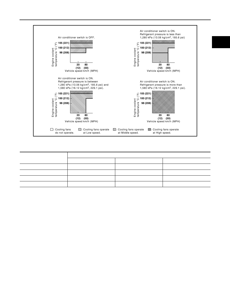
Cooling Fan Operation
Cooling Fan Relay Operation
The ECM controls cooling fan relays in the IPDM E/R through CAN communication line.
JMBIA0179GB
Cooling fan speed
Cooling fan relay
1
2
3
Stop (OFF)
OFF
OFF
OFF
Low (LOW)
ON
OFF
OFF
Middle (MID)
OFF
ON
OFF
High (HI)
OFF
ON
ON
EC-76
< SYSTEM DESCRIPTION >
[VQ35DE]
COOLING FAN CONTROL
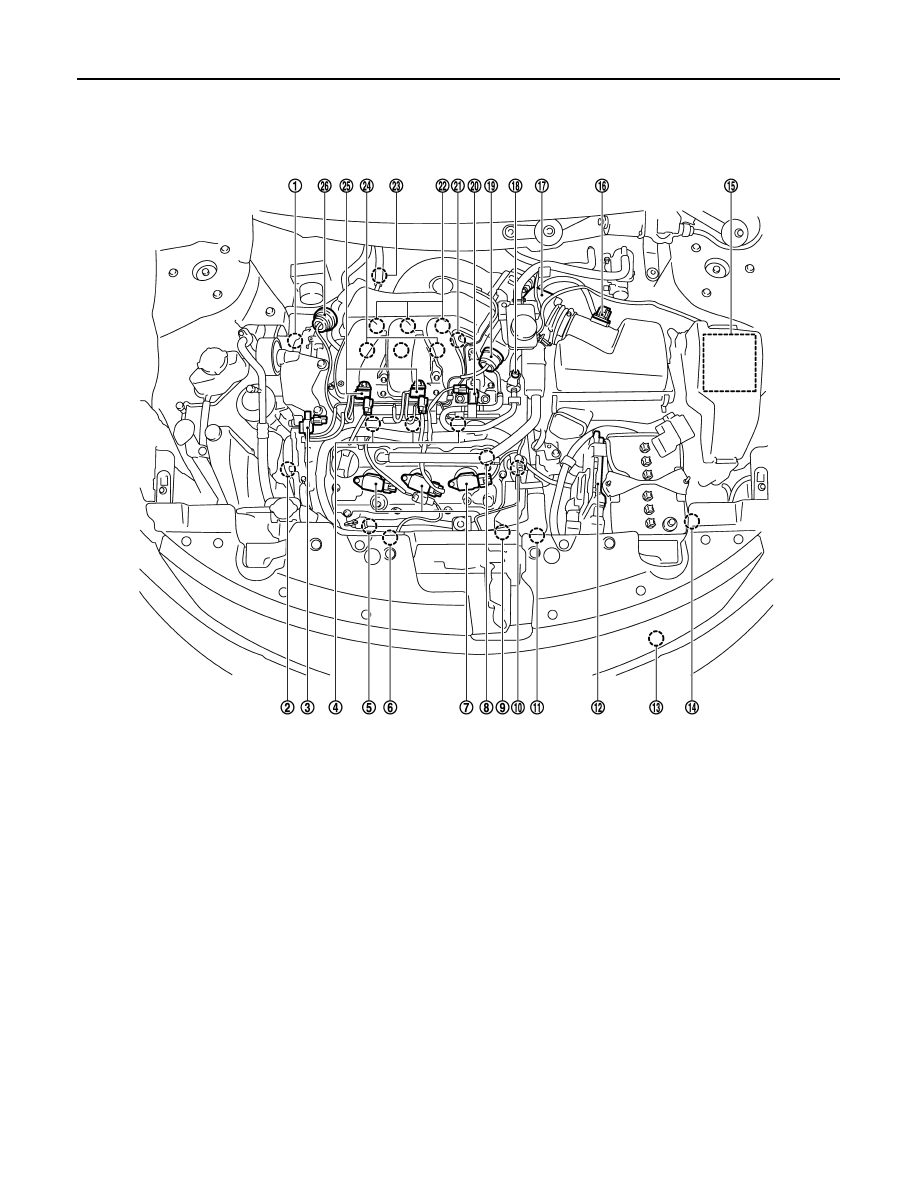
Component Parts Location
INFOID:0000000009719845
1.
Intake valve timing control solenoid
valve (bank 1)
2.
Intake valve timing control solenoid
valve (bank 2)
3.
Electronic controlled engine mount
control solenoid valve
4.
Fuel injector (bank 2)
5.
A/F sensor 1 (bank 2)
6.
Cooling fan motor-2
7.
Ignition coil (with power transistor)
and spark plug (bank 2)
8.
Camshaft position sensor (PHASE)
(bank 2)
9.
Crankshaft position sensor (POS)
10. Engine coolant temperature sensor
11.
Cooling fan motor-1
12. ECM
13. Refrigerant pressure sensor
14. Battery current sensor
15. IPDM E/R
16. Mass air flow sensor (with intake air
temperature sensor)
17. Electric throttle control actuator
18. EVAP service port
19. Power valve actuator 2
20. EVAP canister purge volume control
solenoid valve
21. Camshaft position sensor (PHASE)
(bank 1)
22. Ignition coil (with power transistor)
and spark plug (bank 1)
23. A/F sensor 1 (bank 1)
24. Fuel injector (bank 1)
25. VIAS control solenoid valve 1 and 2
26. Power valve actuator 1
JMBIA1108ZZ
COOLING FAN CONTROL
EC-77
< SYSTEM DESCRIPTION >
[VQ35DE]
C
D
E
F
G
H
I
J
K
L
M
A
EC
N
P
O
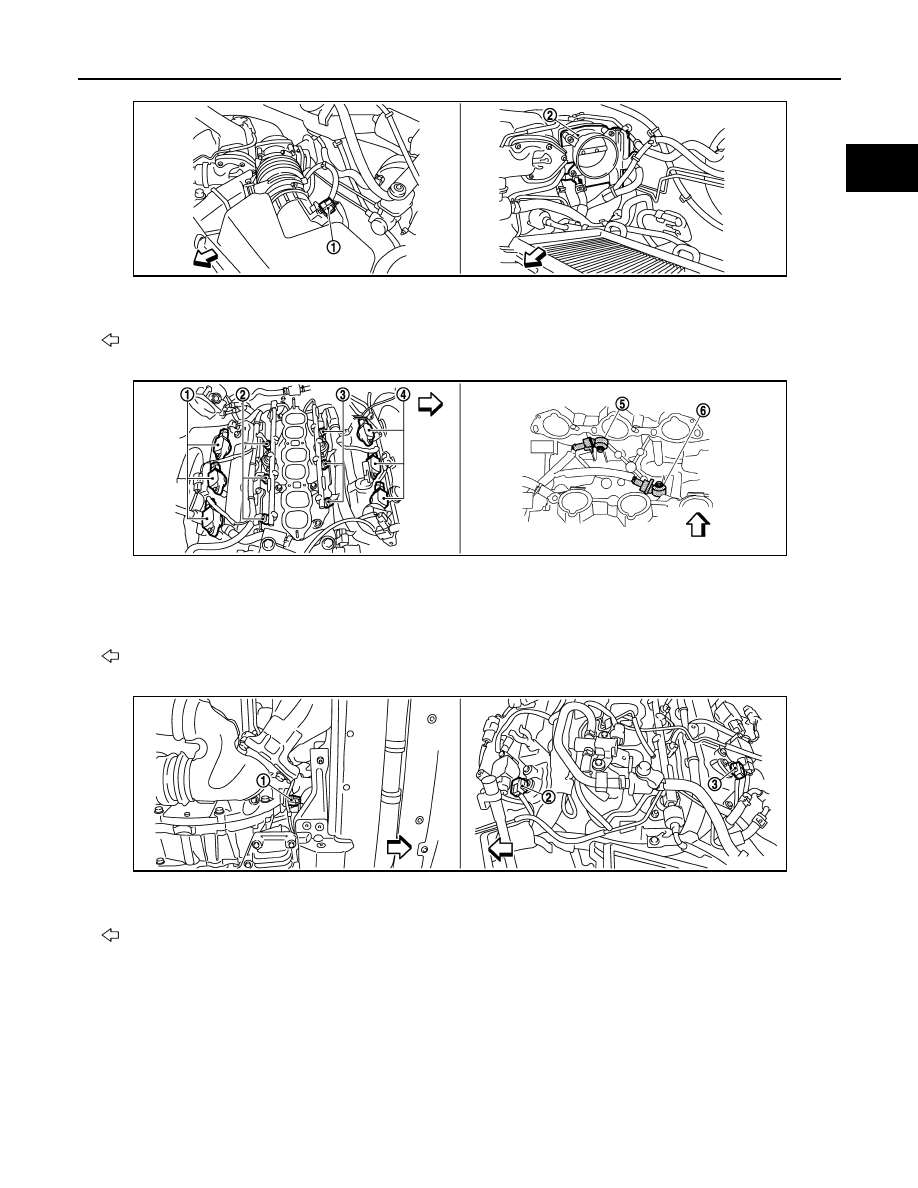
1.
Mas air flow sensor (with intake air
temperature sensor)
2.
Electric throttle control actuator
: Vehicle front
1.
Ignition coil (with power transistor)
and spark plug (bank 1)
2.
Fuel injector (bank 1)
3.
Fuel injector (bank 2)
4.
Ignition coil (with power transistor)
and spark plug (bank 2)
5.
Knock sensor (bank 2)
6.
Knock sensor (bank 1)
: Vehicle front
1.
Crankshaft position sensor (POS)
2.
Camshaft position sensor (PHASE)
(bank 1)
3.
Camshaft position sensor (PHASE)
(bank 2)
: Vehicle front
JMBIA1109ZZ
JMBIA1110ZZ
JMBIA1114ZZ
Нет комментариевНе стесняйтесь поделиться с нами вашим ценным мнением.
Текст