Nissan Murano. Manual — part 873

INL-4
< BASIC INSPECTION >
DIAGNOSIS AND REPAIR WORK FLOW
1.
GET INFORMATION FOR SYMPTOM
1.
Get detailed information from the customer about the symptom (the condition and the environment when
the incident/malfunction occurs).
2.
Check operation condition of the function that is malfunctioning.
>> GO TO 2.
2.
CHECK DTC
1.
Check DTC.
2.
Perform the following procedure if DTC is detected.
-
Record DTC and freeze frame data (Print them out using CONSULT.)
-
Erase DTC.
-
Study the relationship between the cause detected by DTC and the symptom described by the customer.
3.
Check related service bulletins for information.
Are any symptoms described and any DTC detected?
Symptom is described, DTC is detected>>GO TO 3.
Symptom is described, DTC is not detected>>GO TO 4.
Symptom is not described, DTC is detected>>GO TO 5.
3.
CONFIRM THE SYMPTOM
Try to confirm the symptom described by the customer.
Also study the normal operation and fail-safe related to the symptom.
Verify relation between the symptom and the condition when the symptom is detected.
>> GO TO 5.
4.
CONFIRM THE SYMPTOM
Try to confirm the symptom described by the customer.
Verify relation between the symptom and the condition when the symptom is detected.
>> GO TO 6.
5.
PERFORM DTC CONFIRMATION PROCEDURE
Perform DTC CONFIRMATION PROCEDURE for the detected DTC, and then check that DTC is detected
again. At this time, always connect CONSULT to the vehicle, and check self diagnostic results in real time.
If two or more DTCs are detected, refer to DTC INSPECTION PRIORITY CHART, and determine trouble diag-
nosis order.
NOTE:
• Freeze frame data is useful if the DTC is not detected.
• Perform Component Function Check if DTC CONFIRMATION PROCEDURE is not included on Service
Manual. This simplified check procedure is an effective alternative though DTC cannot be detected during
this check.
If the result of Component Function Check is NG, it is the same as the detection of DTC by DTC CONFIR-
MATION PROCEDURE.
Is DTC detected?
YES
>> GO TO 7.
NO
>> Check according to
GI-44, "Intermittent Incident"
.
6.
DETECT MALFUNCTIONING SYSTEM BY SYMPTOM DIAGNOSIS
Detect malfunctioning system according to SYMPTOM DIAGNOSIS based on the confirmed symptom in step
4, and determine the trouble diagnosis order based on possible causes and symptom.
Is the symptom described?
YES
>> GO TO 7.
NO
>> Monitor input data from related sensors or check voltage of related module terminals using CON-
SULT.
7.
DETECT MALFUNCTIONING PART BY DIAGNOSIS PROCEDURE

DIAGNOSIS AND REPAIR WORK FLOW
INL-5
< BASIC INSPECTION >
C
D
E
F
G
H
I
J
K
M
A
B
INL
N
O
P
Inspect according to Diagnosis Procedure of the system.
Is malfunctioning part detected?
YES
>> GO TO 8.
NO
>> Check according to
GI-44, "Intermittent Incident"
.
8.
REPAIR OR REPLACE THE MALFUNCTIONING PART
1.
Repair or replace the malfunctioning part.
2.
Reconnect parts or connectors disconnected during Diagnosis Procedure again after repair and replace-
ment.
3.
Check DTC. If DTC is detected, erase it.
>> GO TO 9.
9.
FINAL CHECK
When DTC is detected in step 2, perform DTC CONFIRMATION PROCEDURE again, and then check that the
malfunction is repaired securely.
When symptom is described by the customer, refer to confirmed symptom in step 3 or 4, and check that the
symptom is not detected.
Is DTC detected and does symptom remain?
YES-1 >> DTC is detected: GO TO 7.
YES-2 >> Symptom remains: GO TO 4.
NO
>> Before returning the vehicle to the customer, always erase DTC.
INL-6
< SYSTEM DESCRIPTION >
INTERIOR ROOM LAMP CONTROL SYSTEM
SYSTEM DESCRIPTION
INTERIOR ROOM LAMP CONTROL SYSTEM
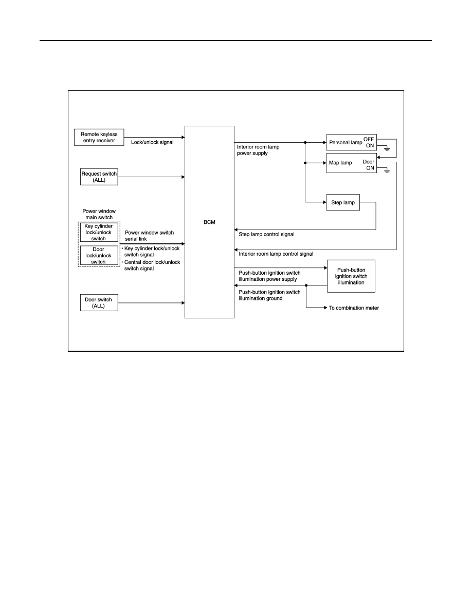
System Diagram
INFOID:0000000009718399
System Description
INFOID:0000000009718400
OUTLINE
• Interior room lamps* are controlled by interior room lamp timer control function of BCM.
*: Map lamp and personal lamp (when map lamp switch is in DOOR position).
• Step lamp is controlled by step lamp control function of BCM.
• Push-button ignition switch illumination is controlled by the push-button ignition switch illumination control
function of BCM.
INTERIOR ROOM LAMP TIMER CONTROL
JPLIA0985GB
INTERIOR ROOM LAMP CONTROL SYSTEM
INL-7
< SYSTEM DESCRIPTION >
C
D
E
F
G
H
I
J
K
M
A
B
INL
N
O
P
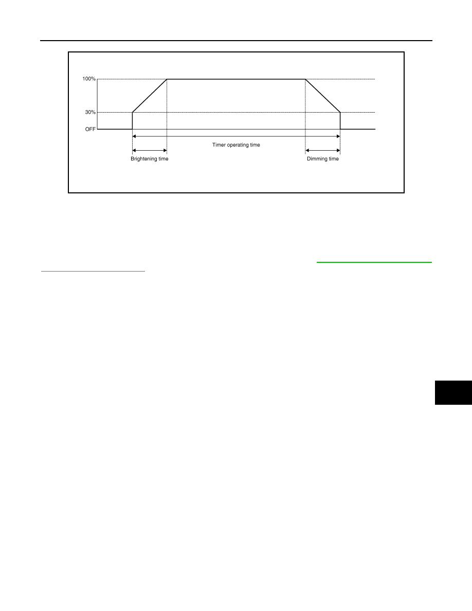
Interior Room Lamp Timer Basic Operation
• The interior room lamp turns ON and OFF (gradual brightening and dimming) by the interior room timer.
• BCM judges the vehicle condition with the following items. It activates the interior room timer.
- Ignition switch status
- Door switch signal (ALL)
- Door lock/unlock signal (Remote keyless entry receiver, each request switch, key cylinder lock/unlock
switch, door lock/unlock switch)
NOTE:
Each function of interior room lamp timer can be set by CONSULT. Refer to
.
Interior Room Lamp ON Operation
• BCM always turns the interior room lamp ON when any door opens.
• BCM activates the interior room timer in any of the following conditions to turn the interior room lamp ON for
a period of time.
- Any door opens before all doors close.
- Ignition switch is turned ON
→
OFF.
- Any door unlock signal is detected when all doors close with ignition switch OFF.
NOTE:
Restart the timer if new condition is input during the timer operating time.
Interior Room Lamp OFF Operation
BCM stops the timer in any of the following conditions to turns the interior room lamp OFF.
• The timer operating time is expired.
• Ignition switch position is other than OFF with all doors close.
• Any door lock operation is detected with all doors close.
STEP LAMP CONTROL
BCM controls the step lamp (ground-side) to turn ON with any door switch ON.
PUSH-BUTTON IGNITION SWITCH ILLUMINATION CONTROL
Push-button Ignition Switch Illumination Basic Operation
• BCM provides the power supply and the ground to turn the push-button ignition switch illumination ON.
• BCM cuts the ground supply while the each illumination (tail lamp) ON. BCM switches to the ground control
with the meter illumination control function.
Push-button Ignition Switch Illumination ON Operation
BCM turns the push-button ignition switch illumination ON in the following conditions.
• Ignition switch ON
• Each illumination (tail lamp) ON
• Any of the following conditions with ignition switch OFF
- Engine start permission is entered.
- Intelligent Key inserted into the key slot.
- Driver door is LOCK
→
UNLOCK.
- Driver door is open.
Push-button Ignition Switch Illumination OFF Operation
JPLIA0093GB
Нет комментариевНе стесняйтесь поделиться с нами вашим ценным мнением.
Текст