Nissan Murano. Manual — part 1449

WCS-18
< SYSTEM DESCRIPTION >
DIAGNOSIS SYSTEM (METER)
NOTE:
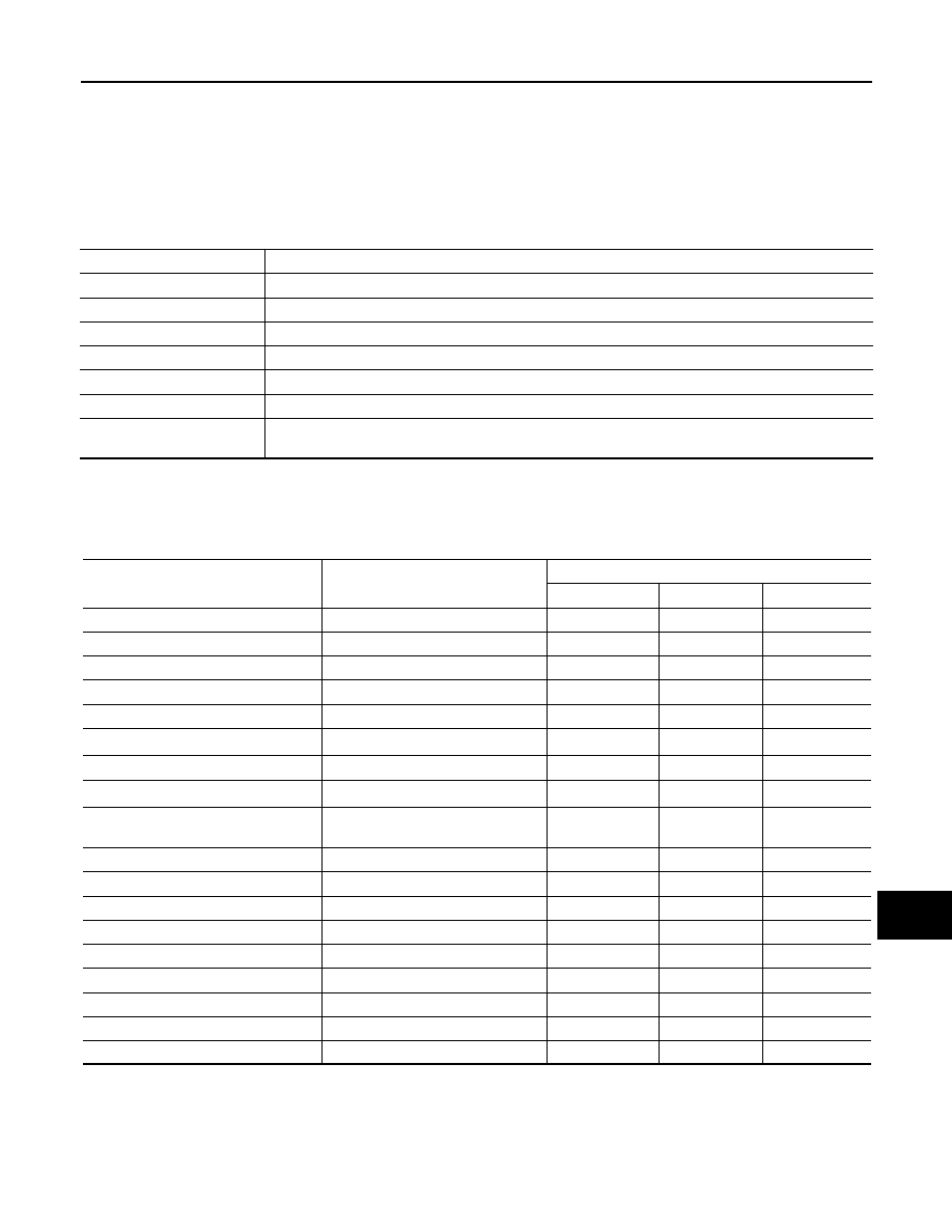
In items displayed on the CONSULT screen, only those listed in the above table are used.
C-ENG W/L
Lighting history of malfunction indicator lamp.
CRUISE IND
Lighting history of CRUISE indicator lamp.
SET IND
Lighting history of SET indicator.
O/D OFF IND
Lighting history of O/D OFF indicator lamp.
4WD W/L
Lighting history of AWD warning lamp.
FUEL W/L
Lighting history of low fuel level warning.
WASHER W/L
Lighting history of low washer fluid warning
AIR PRES W/L
Lighting history of low tire pressure warning lamp.
KEY G/Y W/L
Lighting history of key warning lamp (green/yellow).
KEY R W/L
Lighting history of key warning lamp (red).
CHAGE W/L
Lighting history of charge warning lamp.
BSW W/L
Lighting history of BSW/Blind Spot Intervention warning lamp (yellow).
LDW IND
Lighting history of lane departure warning lamp (yellow) or LDW ON indicator lamp (green).
Display item
Description
WCS
DIAGNOSIS SYSTEM (BCM)
WCS-19
< SYSTEM DESCRIPTION >
C
D
E
F
G
H
I
J
K
L
M
B
A
O
P
DIAGNOSIS SYSTEM (BCM)
COMMON ITEM
COMMON ITEM : CONSULT Function (BCM - COMMON ITEM)
INFOID:0000000010088789
APPLICATION ITEM
CONSULT performs the following functions via CAN communication with BCM.
SYSTEM APPLICATION
BCM can perform the following functions for each system.
NOTE:
It can perform the diagnosis modes except the following for all sub system selection items.
×
: Applicable item
NOTE:
• *1: For models with rain sensor this mode is displayed, but is not used.
• *2: This item is displayed, but is not used.
FREEZE FRAME DATA (FFD)
Diagnosis mode
Function Description
Work Support
Changes the setting for each system function.
Self Diagnostic Result
Displays the diagnosis results judged by BCM.
CAN Diag Support Monitor
Monitors the reception status of CAN communication viewed from BCM.
Data Monitor
The BCM input/output signals are displayed.
Active Test
The signals used to activate each device are forcibly supplied from BCM.
Ecu Identification
The BCM part number is displayed.
Configuration
• Read and save the vehicle specification.
• Write the vehicle specification when replacing BCM.
System
Sub system selection item
Diagnosis mode
Work Support
Data Monitor
Active Test
Door lock
DOOR LOCK
×
×
×
Rear window defogger
REAR DEFOGGER
×
×
Warning chime
BUZZER
×
×
Interior room lamp timer
INT LAMP
×
×
×
Exterior lamp
HEAD LAMP
×
×
×
Wiper and washer
WIPER
×
*
1
×
×
Turn signal and hazard warning lamps
FLASHER
×
×
×
—
AIR CONDITONER*
2
• Intelligent Key system
• Engine start system
INTELLIGENT KEY
×
×
×
Combination switch
COMB SW
×
Body control system
BCM
×
NVIS - NATS
IMMU
×
×
Interior room lamp battery saver
BATTERY SAVER
×
×
×
Back door opener system
TRUNK
×
×
Vehicle security system
THEFT ALM
×
×
×
RAP system
RETAINED PWR
×
Signal buffer system
SIGNAL BUFFER
×
×
TPMS
TPMS (AIR PRESSURE MONITOR)
×
×
×

WCS-20
< SYSTEM DESCRIPTION >
DIAGNOSIS SYSTEM (BCM)
The BCM records the following vehicle condition at the time a particular DTC is detected, and displays on
CONSULT.
NOTE:
*: Power supply position shifts to “LOCK” from “OFF”, when ignition switch is in the OFF position, selector lever is in the P position, and
any of the following conditions are met.
• Closing door
• Opening door
• Door is locked using door request switch
• Door is locked using Intelligent Key
The power supply position shifts to “ACC” when the push-button ignition switch (push switch) is pushed at “LOCK”.
BUZZER
BUZZER : CONSULT Function (BCM - BUZZER)
INFOID:0000000009721361
CONSULT APPLICATION ITEMS
CONSULT screen item
Indication/Unit
Description
Vehicle Speed
km/h
Vehicle speed of the moment a particular DTC is detected
Odo/Trip Meter
km
Total mileage (Odometer value) of the moment a particular DTC is detected
Vehicle Condition
SLEEP>LOCK
Power position status of
the moment a particular
DTC is detected
While turning BCM status from low power consumption mode to
normal mode (Power supply position is “LOCK”*)
SLEEP>OFF
While turning BCM status from low power consumption mode to
normal mode (Power supply position is “OFF”.)
LOCK>ACC
While turning power supply position from “LOCK” to “ACC”
ACC>ON
While turning power supply position from “ACC” to “IGN”
RUN>ACC
While turning power supply position from “RUN” to “ACC” (Vehicle
is stopping and selector lever is except P position.)
CRANK>RUN
While turning power supply position from “CRANKING” to “RUN”
(From cranking up the engine to run it)
RUN>URGENT
While turning power supply position from “RUN“ to “ACC” (Emer-
gency stop operation)
ACC>OFF
While turning power supply position from “ACC” to “OFF”
OFF>LOCK
While turning power supply position from “OFF” to “LOCK”*
OFF>ACC
While turning power supply position from “OFF” to “ACC”
ON>CRANK
While turning power supply position from “IGN” to “CRANKING”
OFF>SLEEP
While turning BCM status from normal mode (Power supply posi-
tion is “OFF”.) to low power consumption mode
LOCK>SLEEP
While turning BCM status from normal mode (Power supply posi-
tion is “LOCK”*) to low power consumption mode
LOCK
Power supply position is “LOCK”*
OFF
Power supply position is “OFF” (Ignition switch OFF)
ACC
Power supply position is “ACC” (Ignition switch ACC)
ON
Power supply position is “IGN” (Ignition switch ON with engine
stopped)
ENGINE RUN
Power supply position is “RUN” (Ignition switch ON with engine
running)
CRANKING
Power supply position is “CRANKING” (At engine cranking)
IGN Counter
0 - 39
The number of times that ignition switch is turned ON after DTC is detected
• The number is 0 when a malfunction is detected now.
• The number increases like 1
→
2
→
3...38
→
39 after returning to the normal condition
whenever ignition switch OFF
→
ON.
• The number is fixed to 39 until the self-diagnosis results are erased if it is over 39.

WCS
DIAGNOSIS SYSTEM (BCM)
WCS-21
< SYSTEM DESCRIPTION >
C
D
E
F
G
H
I
J
K
L
M
B
A
O
P
DATA MONITOR
NOTE:
The following table includes information (items) inapplicable to this vehicle. For information (items) applicable
to this vehicle, refer to CONSULT display items.
ACTIVE TEST
Test item
Diagnosis mode
Description
BUZZER
Data Monitor
Displays BCM input data in real time.
Active Test
Operation of electrical loads can be checked by sending driving signal to them.
Display item
[Unit]
Description
PUSH SW
[On/Off]
Status of push button ignition switch judged by BCM.
UNLK SEN-DR
[On/Off]
Status of unlock sensor judged by BCM.
VEH SPEED 1
[Km/h]
Value of vehicle speed signal received from ABS actuator and electric unit (control unit) with CAN
communication line.
KEY SW-SLOT
[On/Off]
Status of key slot judged by BCM.
TAIL LAMP SW
[On/Off]
Status of each switch judged by BCM using the combination switch readout function.
FR FOG SW
[On/Off]
Status of front fog lamp switch judged by BCM.
DOOR SW-DR
[On/Off]
Status of driver side door switch judged by BCM.
Display item
[Unit]
Description
IGN KEY WARN ALM
The key warning chime operation can be checked by operating the relevant function (On/Off).
SEAT BELT WARN TEST
The seat belt warning chime operation can be checked by operating the relevant function (On/Off).
ID REGIST WARNING
The ID regist warning chime operation can be checked by operating the relevant function (On/Off).
LIGHT WARN ALM
The light warning chime operation can be checked by operating the relevant function (On/Off).
Нет комментариевНе стесняйтесь поделиться с нами вашим ценным мнением.
Текст