Nissan Murano. Manual — part 1423
VTL-48
< REMOVAL AND INSTALLATION >
[WITHOUT 7 INCH DISPLAY]
HEATER CORE
*
: Models for Mexico.
Removal and Installation
INFOID:0000000009721107
REMOVAL
1.
Remove heater & cooling unit assembly. Refer to
.
2.
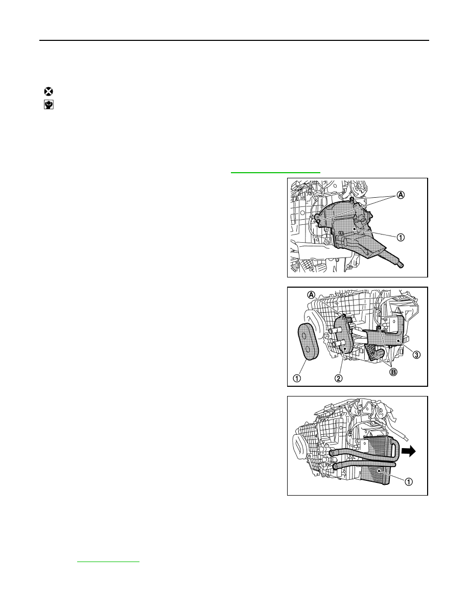
Remove fixing screws (A) and then remove foot duct LH (1).
3.
Remove heater pipe grommet (1).
4.
Remove fixing screw (A) and then remove heater pipe support
(2).
5.
Remove fixing screws (B) and then remove heater pipe cover
(3).
6.
Slide the heater core (1) in the direction shown by the arrow, and
then remove it.
INSTALLATION
Install in the reverse order of removal.
CAUTION:
• Replace the O-ring with a new one. Apply a coat of compressor oil to the O-ring prior to installation.
• Check for refrigerant leakage when charging refrigerant.
NOTE:
• Refer to
when filling the radiator with engine coolant.
• Charge the refrigerant again.
46. Foot door lever
47.
Defroster door lever
48.
Max. cool door lever
49. Air mix door motor (Driver side)
50.
Distributor upper case
51.
Distributor lower case
52. Ventilator door
53.
Foot door
54.
Max. cool door
55. Defroster door
56.
Upper ventilator door
: Always replace after every disassembly.
: N·m (kg-m, in-lb)
JPIIA0579ZZ
JPIIA0580ZZ
JPIIA0581ZZ
DUCT AND GRILLE
VTL-49
< REMOVAL AND INSTALLATION >
[WITHOUT 7 INCH DISPLAY]
C
D
E
F
G
H
J
K
L
M
A
B
VTL
N
O
P
DUCT AND GRILLE
CENTER VENTILATOR GRILLE
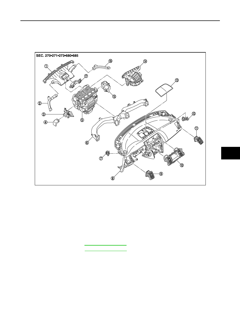
CENTER VENTILATOR GRILLE : Exploded View
INFOID:0000000009721108
CENTER VENTILATOR GRILLE : Removal and Installation
INFOID:0000000009721109
REMOVAL
1.
Remove cluster lid A. Refer to
2.
Remove cluster lid D. Refer to
1.
Defroster nozzle
2.
Side defroster nozzle LH
3.
Foot duct LH
4.
Heater duct
5.
Heater & cooling unit assembly
6.
Ventilator duct
7.
Side defroster grille LH
8.
Instrument panel assembly
9.
Side ventilator grille LH
10. Center ventilator grille assembly
11. Side ventilator grille RH
12. Side defroster grille RH
13. Center speaker grille
14. Blower unit assembly
15. Foot duct RH
16. Side defroster nozzle RH
17. Upper ventilator duct
JPIIA1225ZZ
VTL-50
< REMOVAL AND INSTALLATION >
[WITHOUT 7 INCH DISPLAY]
DUCT AND GRILLE
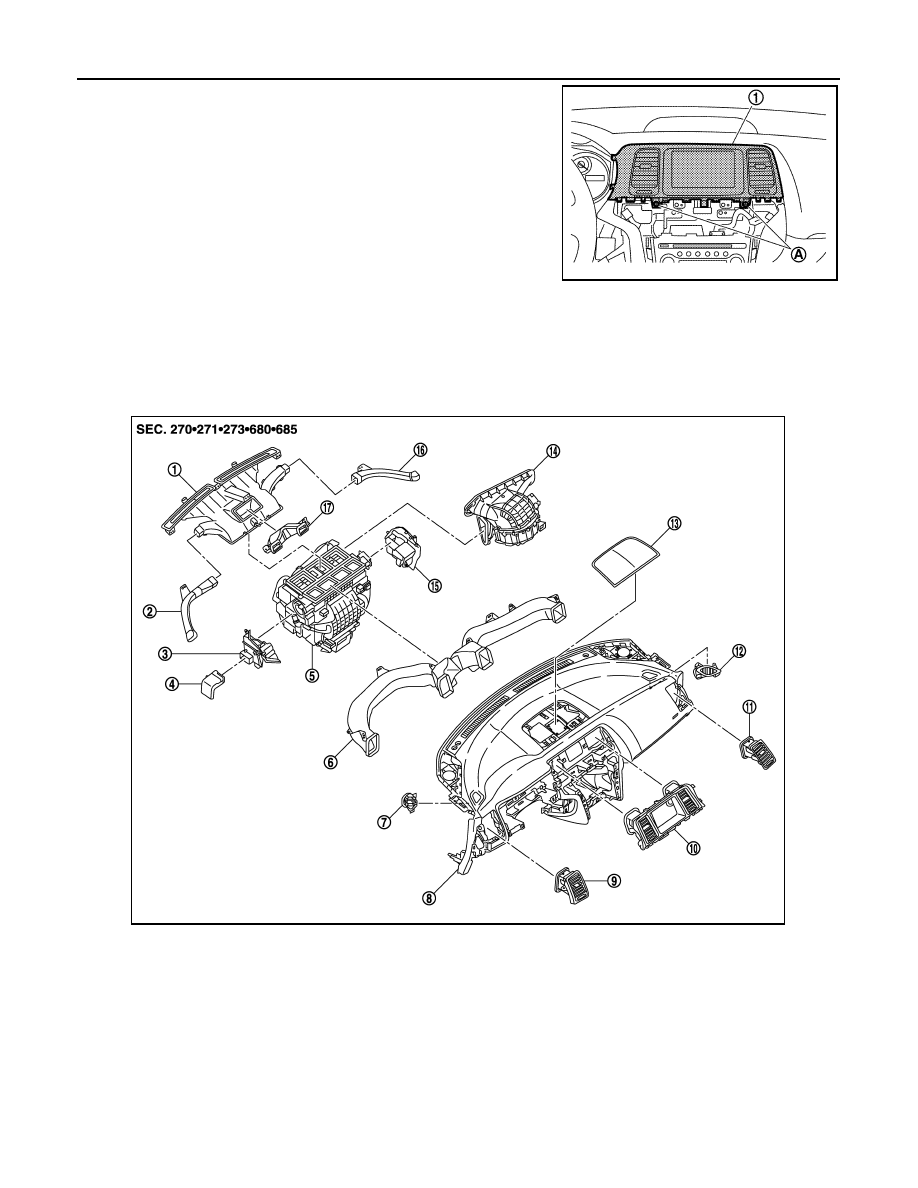
3.
Remove fixing screws (A) and then remove center ventilator
grille assembly (1).
INSTALLATION
Install in the reverse order of removal.
SIDE VENTILATOR GRILLE
SIDE VENTILATOR GRILLE : Exploded View
INFOID:0000000009721110
SIDE VENTILATOR GRILLE : Removal and Installation
INFOID:0000000009721111
REMOVAL
JPIIA0582ZZ
1.
Defroster nozzle
2.
Side defroster nozzle LH
3.
Foot duct LH
4.
Heater duct
5.
Heater & cooling unit assembly
6.
Ventilator duct
7.
Side defroster grille LH
8.
Instrument panel assembly
9.
Side ventilator grille LH
10. Center ventilator grille assembly
11. Side ventilator grille RH
12. Side defroster grille RH
13. Center speaker grille
14. Blower unit assembly
15. Foot duct RH
16. Side defroster nozzle RH
17. Upper ventilator duct
JPIIA1225ZZ
DUCT AND GRILLE
VTL-51
< REMOVAL AND INSTALLATION >
[WITHOUT 7 INCH DISPLAY]
C
D
E
F
G
H
J
K
L
M
A
B
VTL
N
O
P
1.
Remove instrument side finisher (LH/RH). Refer to
.
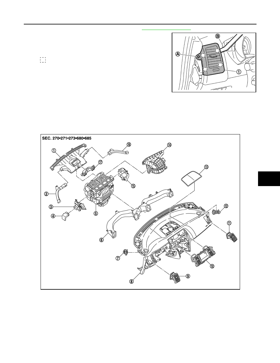
2.
Remove fixing screw (A).
3.
Remove side ventilator grille metal clip using remover tool (B)
and then remove side ventilator grille (1).
INSTALLATION
Install in the reverse order of removal.
SIDE DEFROSTER GRILLE
SIDE DEFROSTER GRILLE : Exploded View
INFOID:0000000009721112
: Metal clip
JPIIA0583ZZ
1.
Defroster nozzle
2.
Side defroster nozzle LH
3.
Foot duct LH
4.
Heater duct
5.
Heater & cooling unit assembly
6.
Ventilator duct
7.
Side defroster grille LH
8.
Instrument panel assembly
9.
Side ventilator grille LH
10. Center ventilator grille assembly
11. Side ventilator grille RH
12. Side defroster grille RH
13. Center speaker grille
14. Blower unit assembly
15. Foot duct RH
16. Side defroster nozzle RH
17. Upper ventilator duct
JPIIA1225ZZ
Нет комментариевНе стесняйтесь поделиться с нами вашим ценным мнением.
Текст