Qashqai J11. Audio, Visual & Navigation System — part 14

AV
U1229 AV CONTROL UNIT
AV-209
< DTC/CIRCUIT DIAGNOSIS >
[NAVIGATION]
C
D
E
F
G
H
I
J
K
L
M
B
A
O
P
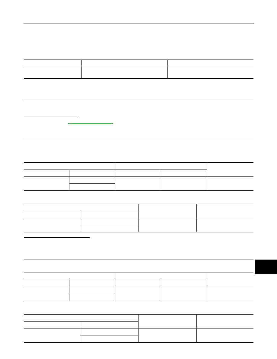
U1229 AV CONTROL UNIT
DTC Logic
INFOID:0000000010435699
DTC DETECTION LOGIC
CONSULT Display
DTC Detection Condition
Possible Cause
iPod CERTIFICATION
[U1229]
iPod authentication chip error.
Replace AV control unit if malfunction occurs
constantly.
Refer to
AV-259, "Removal and Installation"
.

AV-210
< DTC/CIRCUIT DIAGNOSIS >
[NAVIGATION]
U122F AV CONTROL UNIT
U122F AV CONTROL UNIT
DTC Logic
INFOID:0000000010435700
DTC DETECTION LOGIC
CONSULT Display
DTC Detection Condition
Possible Cause
Digital broadcasting connection
error
[U122F]
Communication error with digital audio broadcast
module internal to AV control unit.
Replace AV control unit if malfunction occurs
constantly.
Refer to

AV
U1232 STEERING ANGLE SENSOR
AV-211
< DTC/CIRCUIT DIAGNOSIS >
[NAVIGATION]
C
D
E
F
G
H
I
J
K
L
M
B
A
O
P
U1232 STEERING ANGLE SENSOR
DTC Logic
INFOID:0000000010435701
DTC DETECTION LOGIC
Diagnosis Procedure
INFOID:0000000010435702
1.
ADJUST THE NEUTRAL POSITION OF THE STEERING ANGLE SENSOR
When U1232 is detected, adjust the neutral position of the steering angle sensor.
>> Perform adjustment of the neutral position of the steering angle sensor. Refer to
OUT DRIVER ASSISTANCE SYSTEM : CONSULT Function"
CONSULT Display
DTC Detection Condition
Possible Cause
ST ANG SEN CALIB
[U1232]
The neutral position adjustment of the steering
angle sensor is incomplete.
Adjust neutral position of the steering angle sen-
sor.

AV-212
< DTC/CIRCUIT DIAGNOSIS >
[NAVIGATION]
U1244 GPS ANTENNA
U1244 GPS ANTENNA
DTC Logic
INFOID:0000000010435703
DTC DETECTION LOGIC
Diagnosis Procedure
INFOID:0000000010435704
Regarding Wiring Diagram information, refer to
.
1.
GPS ANTENNA INSPECTION
Visually inspect the GPS antenna and antenna feeder. Refer to
AV-271, "Removal and Installation"
.
Is inspection result normal?
YES
>> GO TO 2.
NO
>> Repair or replace malfunctioning components.
2.
CHECK AV CONTROL UNIT VOLTAGE
1.
Disconnect AV control unit connector M317.
2.
Turn ignition switch ON.
3.
Check voltage between AV control unit connector M317 and ground.
Is inspection result normal?
YES
>> Replace GPS antenna. Refer to
AV-271, "Removal and Installation"
.
NO
>> Replace AV control unit. Refer to
AV-259, "Removal and Installation"
.
CONSULT Display
DTC Detection Condition
Possible Cause
GPS ANTENNA CONN
[U1244]
Open or short to ground is detected in GPS an-
tenna connection.
• GPS antenna disconnection.
• Open or short to ground in GPS antenna signal
circuit.
AV control unit
Ground
Voltage
Connector
Terminal
M317
56
—
5.0 V

AV
U1258 SATELLITE RADIO ANTENNA
AV-213
< DTC/CIRCUIT DIAGNOSIS >
[NAVIGATION]
C
D
E
F
G
H
I
J
K
L
M
B
A
O
P
U1258 SATELLITE RADIO ANTENNA
DTC Logic
INFOID:0000000010435705
DTC DETECTION LOGIC
Diagnosis Procedure
INFOID:0000000010435706
Regarding Wiring Diagram information, refer to
.
1.
SATELLITE ANTENNA INSPECTION
Visually inspect the satellite antenna and antenna feeder. Refer to
.
Is inspection result normal?
YES
>> GO TO 2.
NO
>> Repair or replace malfunctioning components.
2.
CHECK AV CONTROL UNIT VOLTAGE
1.
Turn ignition switch ON.
2.
Check voltage between AV control unit connector M399 and ground.
Is inspection result normal?
YES
>> Replace satellite radio antenna
AV-272, "Removal and Installation"
.
NO
>> Replace AV control unit. Refer to
AV-259, "Removal and Installation"
.
CONSULT Display
DTC Detection Condition
Possible Cause
SXM ANTENNA CONN
[U1258]
Open or short to ground is detected in satellite
antenna connection.
• Satellite antenna disconnection.
• Open or short to ground in satellite antenna
signal circuit.
AV control unit
Ground
Voltage
Connector
Terminal
M399
152
—
5.0 V

AV-214
< DTC/CIRCUIT DIAGNOSIS >
[NAVIGATION]
U1263 USB
U1263 USB
DTC Logic
INFOID:0000000010435707
DTC DETECTION LOGIC
DTC CONFIRMATION PROCEDURE
1.
PERFORM SELF DIAGNOSTIC RESULT
1.
If there is a device connected to the USB interface, disconnect it.
2.
Turn ignition switch ON and wait for 2 seconds or more.
3.
Perform “Self Diagnostic Result” for “MULTI AV”.
Is DTC U1263 displayed?
YES
>> Refer to
.
NO
>> Inspection End.
Diagnosis Procedure
INFOID:0000000010435708
1.
CHECK USB INTERFACE HARNESS
Visually inspect USB interface harness. Refer to
AV-265, "Removal and Installation"
.
Is the inspection result normal?
YES
>> GO TO 2.
NO
>> Replace USB interface harness. Refer to
AV-265, "Removal and Installation"
.
2.
CHECK USB INTERFACE HARNESS
Check USB interface harness. Refer to
.
Is the inspection result normal?
YES
>> Replace AV control unit. Refer to
AV-259, "Removal and Installation"
.
NO
>> Replace USB interface harness. Refer to
AV-265, "Removal and Installation"
.
CONSULT Display
DTC Detection Condition
Possible Cause
USB OVERCURRENT
[U1263]
Overcurrent in USB harness is detected.
• Device connected to USB interface.
• Harness between the AV control unit and USB
interface.

AV
U12AA CONFIGURATION ERROR
AV-215
< DTC/CIRCUIT DIAGNOSIS >
[NAVIGATION]
C
D
E
F
G
H
I
J
K
L
M
B
A
O
P
U12AA CONFIGURATION ERROR
DTC Logic
INFOID:0000000010435709
DTC DETECTION LOGIC
Diagnosis Procedure
INFOID:0000000010435710
1.
PERFORM CONFIGURATION
When U12AA is detected, configuration data must be written.
>> Write configuration data with CONSULT. Refer to
AV-178, "CONFIGURATION (AV CONTROL
CONSULT Display
DTC Detection Condition
Possible Cause
Configuration Error
[U12AA]
AV control unit is not properly configured or con-
figuration is corrupt.
Configuration data needs to be written.
Refer to

AV-216
< DTC/CIRCUIT DIAGNOSIS >
[NAVIGATION]
U1264 ANTENNA AMP.
U1264 ANTENNA AMP.
DTC Logic
INFOID:0000000010435711
DTC DETECTION LOGIC
Diagnosis Procedure
INFOID:0000000010435712
Regarding Wiring Diagram information, refer to
.
1.
AM-FM ANTENNA INSPECTION
Visually inspect the antenna base (AM-FM antenna) and antenna feeder. Refer to
.
Is inspection result normal?
YES
>> GO TO 2.
NO
>> Repair or replace malfunctioning components.
2.
CHECK CONTINUITY BETWEEN AV CONTROL UNIT AND ANTENNA BASE
1.
Turn ignition switch OFF.
2.
Disconnect AV control unit connector M399 and antenna base connector M394.
3.
Check continuity between AV control unit connector M399 and antenna base connector M394.
4.
Check continuity between AV control unit connector M139 and ground.
Is the inspection result normal?
YES
>> GO TO 3.
NO
>> Repair or replace harness or connectors.
3.
CHECK AV CONTROL UNIT VOLTAGE
1.
Connect AV control unit connector M399.
2.
Turn ignition switch ON.
3.
Check voltage between AV control unit connector M399 and ground.
Is the inspection result normal?
YES
>> Replace antenna base. Refer to
AV-272, "Removal and Installation"
.
NO
>> Replace AV control unit. Refer to
AV-259, "Removal and Installation"
.
CONSULT Display
DTC Detection Condition
Possible Cause
FM Antenna error
[U12AB]
Open or short to ground is detected in AM-FM an-
tenna connection.
• AM-FM antenna disconnection.
• Open or short to ground in AM-FM antenna
signal circuit.
AV control unit
Antenna base
Continuity
Connector
Terminal
Connector
Terminal
M399
152
M394
1
Yes
AV control unit
Ground
Continuity
Connector
Terminal
M399
152
—
No
AV control unit
Ground
Voltage
(Approx.)
Connector
Terminal
M399
152
—
5.0 V

AV
U12AC AV CONTROL UNIT
AV-217
< DTC/CIRCUIT DIAGNOSIS >
[NAVIGATION]
C
D
E
F
G
H
I
J
K
L
M
B
A
O
P
U12AC AV CONTROL UNIT
DTC Logic
INFOID:0000000010435713
DTC DETECTION LOGIC
CONSULT Display
DTC Detection Condition
Possible Cause
Display Temperature too High
[U12AC]
Display temperature has exceeded maximum
temperature. Display is switched OFF to avoid ir-
reversible damage.
Replace AV control unit if malfunction occurs
constantly.
Refer to

AV-218
< DTC/CIRCUIT DIAGNOSIS >
[NAVIGATION]
U12AD AV CONTROL UNIT
U12AD AV CONTROL UNIT
DTC Logic
INFOID:0000000010435714
DTC DETECTION LOGIC
CONSULT Display
DTC Detection Condition
Possible Cause
ECU Temperature too High
[U12AD]
AV control unit temperature has exceeded maxi-
mum temperature.
Replace AV control unit if malfunction occurs
constantly.
Refer to
AV-259, "Removal and Installation"
.

AV
U12AE AV CONTROL UNIT
AV-219
< DTC/CIRCUIT DIAGNOSIS >
[NAVIGATION]
C
D
E
F
G
H
I
J
K
L
M
B
A
O
P
U12AE AV CONTROL UNIT
DTC Logic
INFOID:0000000010435715
DTC DETECTION LOGIC
CONSULT Display
DTC Detection Condition
Possible Cause
Internal Amplifier temperature
Warning
[U12AE]
Internal amplifier temperature has exceeded
maximum temperature.
Replace AV control unit if malfunction occurs
constantly.
Refer to

AV-220
< DTC/CIRCUIT DIAGNOSIS >
[NAVIGATION]
U12AF AV CONTROL UNIT
U12AF AV CONTROL UNIT
DTC Logic
INFOID:0000000010435716
DTC DETECTION LOGIC
CONSULT Display
DTC Detection Condition
Possible Cause
CD Mechanism Temperature
Warning
[U12AF]
CD drive temperature has exceeded maximum
temperature. CD drive is switched OFF to avoid
irreversible damage.
Replace AV control unit if malfunction occurs
constantly.
Refer to
AV-259, "Removal and Installation"
.
AV
U1300 AV COMM CIRCUIT
AV-221
< DTC/CIRCUIT DIAGNOSIS >
[NAVIGATION]
C
D
E
F
G
H
I
J
K
L
M
B
A
O
P
U1300 AV COMM CIRCUIT
DTC Logic
INFOID:0000000010435721
DTC DETECTION LOGIC
Diagnosis Procedure
INFOID:0000000010435722
1.
PERFORM SELF DIAGNOSTIC RESULT FOR METER M&A
1.
Turn ignition switch ON and wait for 2 seconds or more.
2.
Perform “Self Diagnostic Result” for “METER M&A”.
Are any DTCs displayed?
YES
>> Refer to
.
NO
>> GO TO 2.
2.
CHECK AV COMMUNICATION CIRCUIT (MCAN L) CONTINUITY
1.
Turn ignition switch OFF.
2.
Disconnect AV control unit connector M49 and combination meter connector M52.
3.
Check continuity between AV control unit connector M49 and combination meter connector M52.
4.
Check continuity between AV control unit connector M49 and ground.
Is the inspection result normal?
YES
>> GO TO 3.
NO
>> Repair or replace harness or connectors.
3.
CHECK AV COMMUNICATION CIRCUIT (MCAN H) CONTINUITY
1.
Check continuity between AV control unit connector M49 and combination meter connector M52.
2.
Check continuity between AV control unit connector M49 and ground.
CONSULT Display
DTC Detection Condition
Possible Cause
AV COMM CIRCUIT
[U1300]
AV communication circuit malfunction (MCAN)
between AV control unit and combination meter.
AV communication circuits between AV control
unit and combination meter.
AV control unit
Combination meter
Continuity
Connector
Terminal
Connector
Terminal
M49
32
M52
48
Yes
39
AV control unit
Ground
Continuity
Connector
Terminal
M49
32
—
No
39
AV control unit
Combination meter
Continuity
Connector
Terminal
Connector
Terminal
M49
31
M52
47
Yes
38
AV control unit
Ground
Continuity
Connector
Terminal
M49
31
—
No
38
AV-222
< DTC/CIRCUIT DIAGNOSIS >
[NAVIGATION]
U1300 AV COMM CIRCUIT
Is the inspection result normal?
YES
>> Replace the AV control unit. Refer to
AV-259, "Removal and Installation"
.
NO
>> Repair or replace harness or connectors.

AV
U1304 CAMERA IMAGE CALIBRATION
AV-223
< DTC/CIRCUIT DIAGNOSIS >
[NAVIGATION]
C
D
E
F
G
H
I
J
K
L
M
B
A
O
P
U1304 CAMERA IMAGE CALIBRATION
DTC Logic
INFOID:0000000010435723
DTC DETECTION LOGIC
Diagnosis Procedure
INFOID:0000000010435724
1.
PERFORM CALIBRATION
When U1304 is detected, perform calibration of camera image.
>> Refer to
AV-181, "CALIBRATING CAMERA IMAGE (AROUND VIEW MONITOR) : Work Proce-
.
CONSULT Display
DTC Detection Condition
Possible Cause
Non-completion of the calibra-
tion
[U1304]
Camera image calibration is incomplete.
Perform calibration of camera image.

AV-224
< DTC/CIRCUIT DIAGNOSIS >
[NAVIGATION]
U1305 CONFIG UNFINISH
U1305 CONFIG UNFINISH
DTC Logic
INFOID:0000000010435725
DTC DETECTION LOGIC
Diagnosis Procedure
INFOID:0000000010435726
1.
PERFORM CONFIGURATION
When U1305 is detected, perform configration of around view monitor control unit.
>> Refer to
AV-179, "CONFIGURATION (AROUND VIEW MONITOR CONTROL UNIT) : Work Pro-
CONSULT Display
DTC Detection Condition
Possible Cause
Non-completion of the configu-
ration
[U1305]
Configuration of around view monitor control unit
is incomplete.
Perform configuration of around view monitor
control unit.
Нет комментариевНе стесняйтесь поделиться с нами вашим ценным мнением.
Текст