Nissan Juke (2014 year). Service Repair Manual — part 74
DLN-112
< UNIT DISASSEMBLY AND ASSEMBLY >
[TRANSFER: TY21B]
DRIVE PINION
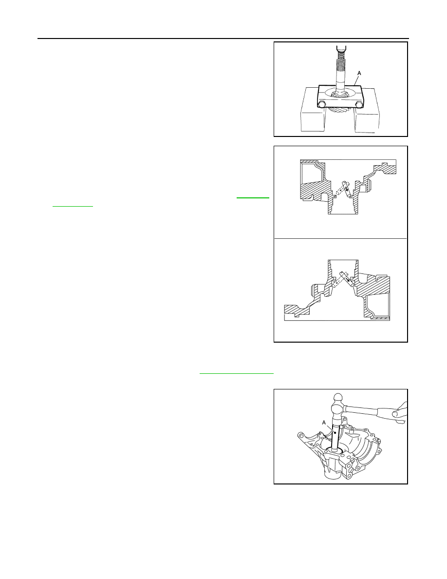
10. Remove inner race of pinion bearing (front) from drive pinion
with the replacer (A) (Commercial service tool).
11. Tap the outer race of pinion bearing (rear) from transfer case
with a brass rod to remove outer race of pinion bearing (rear).
CAUTION:
Never damage transfer case.
12. Remove drive pinion adjusting shim.
13. Perform inspection after disassembly. Refer to
Assembly
INFOID:0000000009751163
1.
Select drive pinion adjusting shim. Refer to
.
2.
Install selected drive pinion adjusting shim to transfer case.
3.
Install outer race of pinion bearing (rear) to the transfer case
with the drift (A) [SST: ST37830000 (
—
)].
CAUTION:
• Never reuse pinion bearing.
• Apply gear oil to the pinion bearing.
JPDIE0028ZZ
JSDIA2200ZZ
JSDIA2201ZZ
Revision: 2013 October
2014 JUKE

DRIVE PINION
DLN-113
< UNIT DISASSEMBLY AND ASSEMBLY >
[TRANSFER: TY21B]
C
E
F
G
H
I
J
K
L
M
A
B
DLN
N
O
P
4.
Install inner race of pinion bearing (front) to drive pinion with the
drift (A) [SST: ST35272000 (J-26092)].
CAUTION:
• Never reuse pinion bearing.
• Apply gear oil to the pinion bearing.
5.
Assemble inner race of pinion bearing (rear) into the transfer
case.
CAUTION:
• Never reuse pinion bearing.
• Apply gear oil to the pinion bearing.
6.
Using the drifts (A) (Commercial service tool), install drive pinion
oil seal (1) to transfer case within the dimension (L) shown as
follows.
CAUTION:
• Never reuse oil seal.
• When installing, never incline oil seal.
• Apply multi-purpose grease onto oil seal lips, and gear oil
onto the circumference.
7.
Assemble a collapsible spacer onto the drive pinion.
CAUTION:
Never reuse the collapsible spacer.
8.
Assemble drive pinion assembly into the transfer case, and then install companion flange to drive pinion.
NOTE:
Align matching marks (A) on the thread edge of drive pinion and
companion flange, and install companion flange if drive pinion is
reused.
9.
Tap the companion flange (1) with a plastic hammer as far as
the pinion lock nut can be tightened.
CAUTION:
Never damage drive pinion oil seal.
10. Apply anti-corrosive oil to the thread and seat of the pinion lock
nut, and temporarily tighten pinion lock nut to the drive pinion.
CAUTION:
Never reuse pinion lock nut.
JSDIA2196ZZ
L
: 0 – 0.6 mm (0 – 0.024 in)
JSDIA2509ZZ
JSDIA2505ZZ
JSDIA2510ZZ
Revision: 2013 October
2014 JUKE
DLN-114
< UNIT DISASSEMBLY AND ASSEMBLY >
[TRANSFER: TY21B]
DRIVE PINION
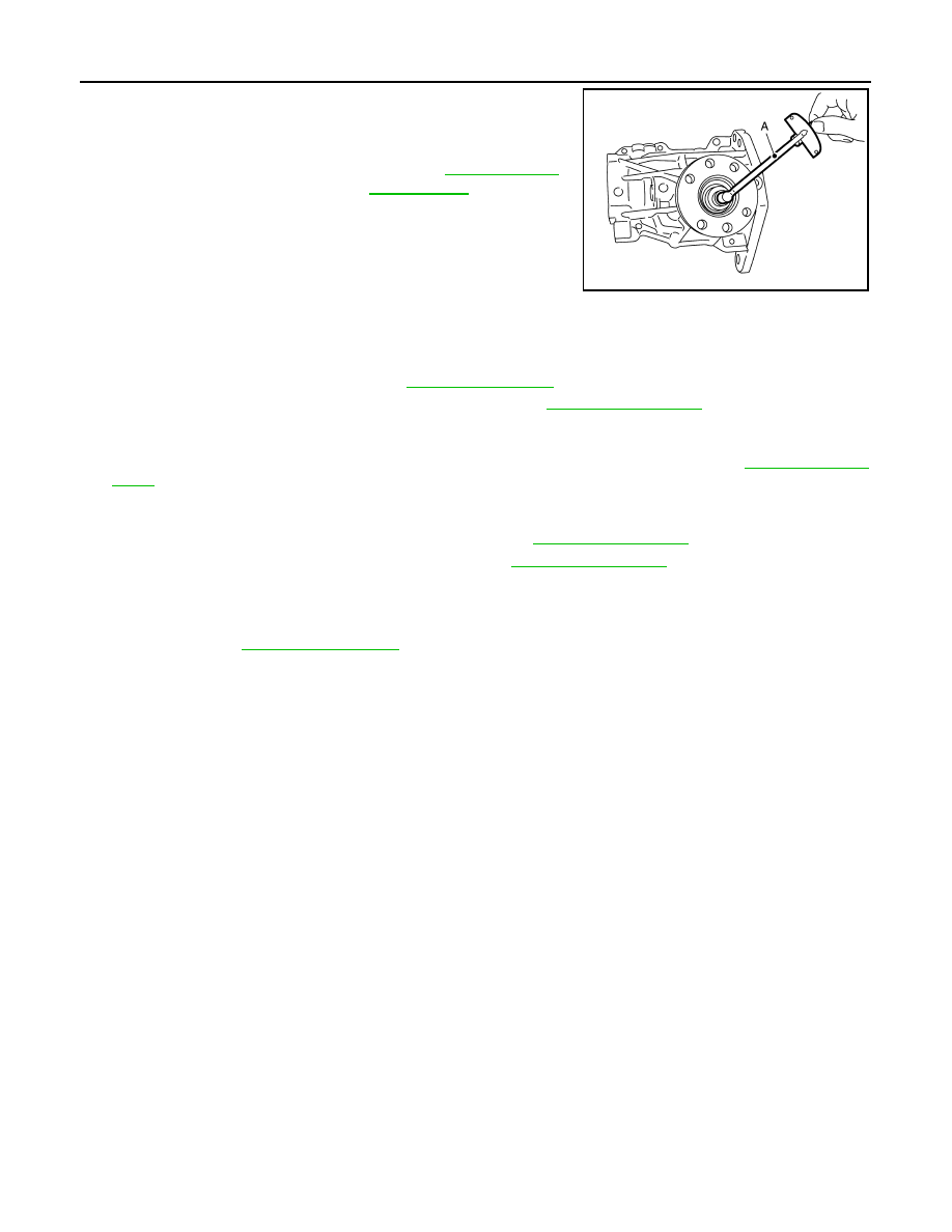
11. Tighten pinion lock nut within the specified torque range with the
preload gauge (A) [SST: ST3127S000 (J-25765-A)] so that the
drive pinion bearing preload is within standard.
CAUTION:
• Start the tightening of pinion lock nut from lower limit of
the specified torque. Check the preload every 5
°
to 10
°
while tightening the pinion lock nut.
• Replace the collapsible spacer and tighten it again to
adjust if preload exceeds the specified value. Never
loosen pinion lock nut to adjust preload.
• After adjustment, rotate the drive pinion back and forth from 2 to 3 times to check for unusual
noise, sticking, binding, and so on.
12. Install ring gear shaft assembly. Refer to
13. Install transfer cover to check and adjust each part. Refer to
CAUTION:
Never apply liquid gasket.
14. Check backlash, tooth contact, total preload and companion flange runout. Refer to
CAUTION:
Measure the total preload without the transfer case oil seal.
15. Reinstall transfer cover for applying liquid gasket. Refer to
.
16. Install the transfer case oil seal (left and right). Refer to
Adjustment
INFOID:0000000009751164
Selecting drive pinion adjusting shim, and checking backlash, tooth contact, total preload and companion
flange runout, refer to
.
Inspection
INFOID:0000000009751165
INSPECTION AFTER DISASSEMBLY
Check items below. If necessary, replace them with new ones.
Gear and Shaft
Check gear face and shaft for wear, cracks, damage, and seizure.
CAUTION:
Replace ring gear and drive pinion as a set (hypoid gear set) if any malfunction is detected on the ring
gear or drive pinion.
Bearing
Check for seizure, peeling, wear, corrosion, sticking, unusual noise, roughness in hand turning, and other
damage.
CAUTION:
Always replace inner race and outer race as a pair when replacing the bearing.
Shim
Check for seizure, damage, and unusual wear.
Drive pinion bearing preload
: Refer to
JSDIA2500ZZ
Revision: 2013 October
2014 JUKE

TRANSFER CASE
DLN-115
< UNIT DISASSEMBLY AND ASSEMBLY >
[TRANSFER: TY21B]
C
E
F
G
H
I
J
K
L
M
A
B
DLN
N
O
P
TRANSFER CASE
Exploded View
INFOID:0000000009751166
1.
Pinion lock nut
2.
Companion flange
3.
Drive pinion oil seal
4.
Pinion bearing (rear)
5.
Transfer case
6.
Gasket
7.
Filler plug
8.
Collapsible spacer
9.
Drive pinion adjusting shim
10. Pinion bearing (front)
11.
Drive pinion
12. Ring gear
13. Ring gear shaft
14. Ring gear bearing (right)
15. Ring gear bearing adjusting shim
(right)
16. Spacer (right)
17. Transfer case oil seal (right)
18. Drive shaft oil seal
19. Transfer cover
20. Oil defense
21. Ring gear bearing (left)
22. Ring gear bearing adjusting shim
(left)
23. Spacer (left)
24. Transfer case oil seal (left)
25. Drain plug
26. Dowel pin
A.
Oil seal lip
B.
Transfer case mounting face
: Always replace after every disassembly.
: Select with proper thickness.
: N·m (kg-m, in-lb)
: N·m (kg-m, ft-lb)
: Apply gear oil.
: Apply multi purpose grease
JSDIA2491GB
Revision: 2013 October
2014 JUKE

DLN-116
< UNIT DISASSEMBLY AND ASSEMBLY >
[TRANSFER: TY21B]
TRANSFER CASE
Disassembly
INFOID:0000000009751167
1.
Remove transfer cover mounting bolts.
2.
Lightly tap position (A) of transfer cover with a plastic hammer to
remove transfer cover.
CAUTION:
When tapping of transfer cover, be sure to tap the back of
cover.
3.
Remove transfer case oil seal (right and left).
4.
Remove ring gear shaft assembly. Refer to
NOTE:
When the ring gear shaft removed, the following parts are simul-
taneously removed:
• Spacer (right and left)
• Ring gear bearing adjusting shim (right and left)
• Outer race of ring gear bearing (right and left)
5.
Remove drive pinion assembly from transfer case. Refer to
6.
Tap the outer races of pinion bearing (front and rear) from trans-
fer case with a brass rod to remove outer races of pinion bearing
(front and rear).
CAUTION:
Never damage transfer case.
7.
Remove drive pinion adjusting shim.
8.
Remove dowel pin.
CAUTION:
Never remove dowel pin, if it is not necessary to replace.
9.
Remove the filler plug and drain plug from the transfer case, and
then remove each gasket.
10. Remove oil defense from transfer cover.
11. Perform inspection after disassembly. Refer to
Assembly
INFOID:0000000009751168
1.
Install the oil defense to transfer cover.
2.
Install gaskets onto filler plug and drain plug and install them into transfer case.
CAUTION:
• Never reuse gasket.
• Install filler plug after oil is filled.
3.
Install the dowel pin to transfer case.
CAUTION:
Never reuse the dowel pin.
4.
Select drive pinion adjusting shim, and install it to transfer case. Refer to
.
: Apply anti-corrosive oil.
: Apply Genuine Silicone RTV or equivalent. Refer to
GI-24, "Recommended Chemical Products and Sealants"
.
JSDIA2199ZZ
JSDIA2200ZZ
Revision: 2013 October
2014 JUKE

TRANSFER CASE
DLN-117
< UNIT DISASSEMBLY AND ASSEMBLY >
[TRANSFER: TY21B]
C
E
F
G
H
I
J
K
L
M
A
B
DLN
N
O
P
5.
Install outer race of pinion bearing (front) to the transfer case
with the drift (A) [SST: ST37830000 (
—
)].
CAUTION:
• Never reuse pinion bearing.
• Apply gear oil to the pinion bearing.
6.
Install outer race of pinion bearing (rear) to transfer case with
the drift (A) [SST: ST33230000 (J-25805-01)].
CAUTION:
• Never reuse pinion bearing.
• Apply gear oil to the pinion bearing.
7.
Install drive pinion assembly to transfer case. Refer to
.
8.
Install ring gear shaft assembly to transfer case. Refer to
.
9.
Set the drifts (A and B) to right and left side spacers individually.
Compress ring gear shaft assembly with ring gear bearing to
install transfer cover to transfer case.
CAUTION:
• Never apply gasket fluid on the mounting surface.
• Clean the mounting surface of transfer case and transfer
cover to degrease sufficiently.
• The drift shall be placed on the center of the spacers.
• The pressure shall be as low as to install ring gear shaft
assembly into transfer case. The maximum pressure shall be 10 kN (1 ton, 1.0 Imp ton).
• If the adjusting shims and spacers are installed by tapping, the transfer cover may be damaged.
Avoid tapping.
10. Check backlash, tooth contact, and total preload. Refer to
.
CAUTION:
Measure the total preload without the transfer case oil seals.
11. Remove transfer cover. Refer to
.
12. Apply liquid gasket (1) to mating surface of transfer cover.
• Use Genuine Silicone RTV or equivalent. Refer to
"Recommended Chemical Products and Sealants"
CAUTION:
• Remove old gasket adhering to the mounting surfaces.
Also remove any moisture, oil, or foreign material adher-
ing to the mounting surfaces.
• The width of sealant bend is 2 – 3 mm (0.08 – 0.012 in).
• Overlap both ends of the bead for at least 3 mm (0.012 in).
• Immediately install transfer cover after installing applying
gasket.
JSDIA2201ZZ
JSDIA2202ZZ
A
: Drift (Commercial service tool)
B
: Drift (Commercial service tool)
JSDIA1105ZZ
JSDIA2203ZZ
Revision: 2013 October
2014 JUKE

DLN-118
< UNIT DISASSEMBLY AND ASSEMBLY >
[TRANSFER: TY21B]
TRANSFER CASE
13. Set the drifts (A and B) to right and left side spacers individually.
Compress ring gear shaft assembly with ring gear bearing to
install transfer cover to transfer case.
CAUTION:
• Immediately install after applying gasket.
• The drift shall be placed on the center of the spacers.
• The pressure shall be as low as to install ring gear shaft
assembly into transfer case. The maximum pressure shall
be 10 kN (1 ton, 1.0 Imp ton).
• If the adjusting shims and spacers are installed by tapping, the transfer cover may be damaged.
Avoid tapping.
14. Tighten transfer cover mounting bolts to the specified torque.
15. Using the drifts (A and B), install transfer case oil seal (left) (1)
within the dimension (L) shown as follows.
CAUTION:
• Never reuse oil seals.
• When installing, never incline oil seals.
• Apply multi-purpose grease onto oil seal lips, and gear oil
onto the circumference of oil seal.
• Immediately install after installing transfer cover.
• After installing oil seal, immediately wipe out gasket squeezed out inward of transfer case.
16. Using the drifts (A) [SST: ST35271000 (J-26091)], install transfer
case oil seal (right) (1) within the dimension (L) shown as fol-
lows.
CAUTION:
• Never reuse oil seals.
• When installing, never incline oil seals.
• Apply multi-purpose grease onto oil seal lips, and gear oil
onto the circumference of oil seal.
• Immediately install after installing transfer cover.
• After installing oil seal, immediately wipe out gasket
squeezed out inward of transfer case.
Inspection
INFOID:0000000009751169
INSPECTION AFTER DISASSEMBLY
Check items below. If necessary, replace them with new ones.
Case and Cover
Check the cracks, damages, and bearing mounting surface for wear.
CAUTION:
Replace transfer case and transfer cover as a set if any malfunction is detected on transfer case or
transfer cover.
A
: Drift (Commercial service tool)
B
: Drift (Commercial service tool)
A
: Drift (Commercial service tool)
B
: Drift [SST: ST27863000 (
—
)]
L
: 1.0 – 1.6 mm (0.040 – 0.063 in)
JSDIA1105ZZ
JSDIA2511ZZ
L
: 0 – 0.6 mm (0 – 0.024 in)
JSDIA2512ZZ
Revision: 2013 October
2014 JUKE

SERVICE DATA AND SPECIFICATIONS (SDS)
DLN-119
< SERVICE DATA AND SPECIFICATIONS (SDS)
[TRANSFER: TY21B]
C
E
F
G
H
I
J
K
L
M
A
B
DLN
N
O
P
SERVICE DATA AND SPECIFICATIONS (SDS)
SERVICE DATA AND SPECIFICATIONS (SDS)
General Specifications
INFOID:0000000009751170
Preload Torque
INFOID:0000000009751171
Unit: N·m (kg-m, in-lb)
Backlash
INFOID:0000000009751172
Unit: mm (in)
Companion Flange Runout
INFOID:0000000009751173
Unit: mm (in)
Applied model
MR16DDT
Transfer model
TY21B
Oil capacity (Approx.)
(US pt, lmp pt)
0.37 (3/4, 5/8)
Gear ratio
0.404
Number of teeth
Ring gear
42
Drive pinion
17
Item
Standard
Drive pinion bearing preload
0.30 – 0.80 (0.03 – 0.08, 3.0 – 7.0)
Total preload
With all oil seals
P
1
+ 0.55 – 0.80 (0.06 – 0.08, 5.0 – 7.0)
Without transfer case oil seal
P
1
+ 0.35 – 0.60 (0.04 – 0.06, 3.0 – 5.0)
Item
Standard
Ring gear to drive pinion
0.13 – 0.18 (0.0051 – 0.0071)
Item
Limit
Companion flange face (inner side of the propeller shaft bolt holes)
0.15 (0.0059)
Inside of companion flange (socket diameter)
0.2 (0.008)
Revision: 2013 October
2014 JUKE

DLN-120
< PRECAUTION >
[REAR PROPELLER SHAFT: 3F
φ
16-ETJ75]
PRECAUTIONS
PRECAUTION
PRECAUTIONS
Precautions for Removing of Battery Terminal
INFOID:0000000010288773
• When removing the 12V battery terminal, turn OFF the ignition
switch and wait at least 30 seconds.
NOTE:
ECU may be active for several tens of seconds after the ignition
switch is turned OFF. If the battery terminal is removed before ECU
stops, then a DTC detection error or ECU data corruption may
occur.
• For vehicles with the 2-batteries, be sure to connect the main bat-
tery and the sub battery before turning ON the ignition switch.
NOTE:
If the ignition switch is turned ON with any one of the terminals of
main battery and sub battery disconnected, then DTC may be
detected.
• After installing the 12V battery, always check "Self Diagnosis Result" of all ECUs and erase DTC.
NOTE:
The removal of 12V battery may cause a DTC detection error.
Service Notice or Precautions for Rear Propeller Shaft
INFOID:0000000009751174
• Replace the propeller shaft assembly if there is a breakage or deflection on tube.
• Never hit the tube or apply an impact on it during repair service. Never damage the tube as well.
• The joint cannot be disassembled. Never disassemble it.
• If constant velocity joint was bent during propeller shaft assembly removal, installation, or transportation, its
boot may be damaged. Wrap boot interference area to metal part with shop cloth or rubber to protect boot
from breakage.
SEF289H
Revision: 2013 October
2014 JUKE

NOISE, VIBRATION AND HARSHNESS (NVH) TROUBLESHOOTING
DLN-121
< SYMPTOM DIAGNOSIS >
[REAR PROPELLER SHAFT: 3F
φ
16-ETJ75]
C
E
F
G
H
I
J
K
L
M
A
B
DLN
N
O
P
SYMPTOM DIAGNOSIS
NOISE, VIBRATION AND HARSHNESS (NVH) TROUBLESHOOTING
NVH Troubleshooting Chart
INFOID:0000000009751175
Use the chart below to find the cause of the symptom. If necessary, repair or replace these parts.
×
: Applicable
Reference
—
—
NV
H
of
R
E
A
R
FI
NA
L D
R
IV
E
in
th
is
se
ct
ion
N
V
H
in F
A
X
, RAX,
FSU and RSU section
NV
H
in
WT s
e
cti
on
NV
H
in
WT s
e
cti
on
NV
H
in
F
A
X
an
d R
A
X
se
c
tio
n
NV
H
in
B
R
s
e
c
tio
n
NV
H
in
S
T
s
e
c
ti
o
n
Possible cause and SUSPECTED PARTS
Un
ev
en
rot
a
ti
ng
to
rqu
e
Cen
ter be
ari
n
g i
mpro
p
e
r in
st
a
lla
ti
on
Exce
ss
iv
e c
en
te
r be
ari
ng
ax
ia
l e
nd
pl
ay
Cen
ter be
ari
n
g mo
un
ti
n
g
(i
ns
ul
at
o
r)
c
rac
ks
, d
a
m
a
g
e
or d
e
te
rio
rat
io
n
Exce
ss
iv
e j
o
in
t a
n
g
le
Rot
a
ti
on
im
ba
lan
c
e
Exce
ss
iv
e ru
no
ut
DIF
F
ERENTI
AL
AX
LE A
N
D
SUSPENSION
TI
RE
ROAD W
H
EEL
DRIV
E SHAFT
BRA
K
E
ST
EERING
Symptom
Noise
×
×
×
×
×
×
×
×
×
×
×
×
×
×
Shake
×
×
×
×
×
×
×
×
Vibration
×
×
×
×
×
×
×
×
×
×
×
Revision: 2013 October
2014 JUKE

DLN-122
< PERIODIC MAINTENANCE >
[REAR PROPELLER SHAFT: 3F
φ
16-ETJ75]
REAR PROPELLER SHAFT
PERIODIC MAINTENANCE
REAR PROPELLER SHAFT
Inspection
INFOID:0000000009751176
APPEARANCE AND NOISE
• Check the propeller shaft tube surface for dents or cracks. If damaged, replace propeller shaft assembly.
• If center bearing is noisy or damaged, replace propeller shaft assembly.
VIBRATION
If vibration is present at high speed, inspect propeller shaft runout first.
1.
With a dial indicator, measure propeller shaft runout at runout
measuring points by rotating final drive companion flange with
hands.
• Propeller shaft runout measuring point (Point “ ”)
2.
If runout still exceeds specifications, separate propeller shaft at
final drive companion flange or transfer companion flange; then
change the phase between companion flange and propeller
shaft by the one bolt hole at a time and install propeller shaft.
3.
Check runout again. If runout still exceeds specifications,
replace propeller shaft assembly.
4.
Check the vibration by driving vehicle.
Propeller shaft runout
: Refer to
.
JPDID0419ZZ
: Front
Dimension
A: 542 mm (21.34 in)
B: 516.5 mm (20.33 in)
JSDIA2286ZZ
Revision: 2013 October
2014 JUKE

REAR PROPELLER SHAFT
DLN-123
< REMOVAL AND INSTALLATION >
[REAR PROPELLER SHAFT: 3F
φ
16-ETJ75]
C
E
F
G
H
I
J
K
L
M
A
B
DLN
N
O
P
REMOVAL AND INSTALLATION
REAR PROPELLER SHAFT
Exploded View
INFOID:0000000009751177
Removal and Installation
INFOID:0000000009751178
REMOVAL
1.
Shift the transaxle to the neutral position, and then release the parking brake.
2.
Put matching marks on propeller shaft flange yoke and final drive companion flanges.
CAUTION:
For matching marks, use paint. Never damage propeller shaft flange yoke and final drive compan-
ion flange.
3.
Put matching marks on propeller shaft flange yoke and transfer companion flanges.
CAUTION:
For matching marks, use paint. Never damage propeller shaft flange yoke and transfer companion
flange.
4.
Loosen mounting nuts of center bearing mounting bracket.
NOTE:
Tighten mounting nuts temporarily.
5.
Remove propeller shaft assembly fixing bolts and nuts.
6.
Remove center bearing mounting bracket fixing nuts.
7.
Remove propeller shaft assembly.
CAUTION:
• This procedure requires 2 workers. Constant velocity joint must be handled with care.
1.
Propeller shaft assembly
: Vehicle front
: N·m (kg-m, ft-lb)
: Always replace after every disassembly.
JPDID0420GB
Revision: 2013 October
2014 JUKE

DLN-124
< REMOVAL AND INSTALLATION >
[REAR PROPELLER SHAFT: 3F
φ
16-ETJ75]
REAR PROPELLER SHAFT
• If constant velocity joint was bent during propeller shaft
assembly removal, installation, or transportation, its boot
(1) may be damaged. Wrap boot interference area to metal
part (2) with shop cloth or rubber to protect boot from
breakage.
• Since no retaining pin is included in sliding direction, the
boot may be damaged or dropped if the constant velocity
joint is slid out 25 mm (0.98 in) or more from the original
length. Therefore, handle constant velocity joint by slid-
ing it inward.
8.
Perform inspection after removal. Refer to
INSTALLATION
Note the following, and install in the reverse order of removal.
• Align matching marks to install propeller shaft assembly to final drive and transfer companion flanges.
• To install, adjust front and rear position of mount bracket to avoid deflection (front-rear direction of the vehi-
cle) to the center bearing insulator.
• Perform inspection after installation. Refer to
• After tightening the bolts and nuts to the specification torque,
check that the bolts (3) on the flange side is tightened as shown in
the figure.
• If propeller shaft assembly or final drive assembly has been replaced, connect them as follows:
CAUTION:
Constant velocity joint of a new propeller shaft has a pre-
installed protector (1). Protector must be removed after
installing propeller shaft.
PDIA0982J
PDIA0983J
1.
Final drive assembly
2.
Propeller shaft assembly
JSDIA0196ZZ
JSDIA2289ZZ
Revision: 2013 October
2014 JUKE

REAR PROPELLER SHAFT
DLN-125
< REMOVAL AND INSTALLATION >
[REAR PROPELLER SHAFT: 3F
φ
16-ETJ75]
C
E
F
G
H
I
J
K
L
M
A
B
DLN
N
O
P
1.
Install propeller shaft (1) while aligning its matching mark (A) of
propeller shaft with the matching mark (B) of final drive (2) on
the joint as close as possible.
2.
Temporary tighten bolts and nuts.
3.
Press down propeller shaft (1) with matching mark (C) of final
drive (2) facing upward. Then tighten fixing bolts and nuts to the
specified torque.
Inspection
INFOID:0000000009751179
INSPECTION AFTER REMOVAL
Appearance
Check the propeller shaft for bend and damage. If damage is detected, replace propeller shaft assembly.
Propeller Shaft Runout
Check propeller shaft runout at measuring points with a dial indica-
tor. If runout exceeds specifications, replace propeller shaft assem-
bly.
• Propeller shaft runout measuring point (Point “ ”)
Journal Axial Play
JSDIA2287ZZ
JSDIA2288ZZ
Propeller shaft runout
: Refer to
.
JSDIA0193ZZ
: Front
Dimension
A: 542 mm (21.34 in)
B: 516.5 mm (20.33 in)
JSDIA2286ZZ
Revision: 2013 October
2014 JUKE

DLN-126
< REMOVAL AND INSTALLATION >
[REAR PROPELLER SHAFT: 3F
φ
16-ETJ75]
REAR PROPELLER SHAFT
As shown in the figure, while fixing yoke on one side, check axial
play of joint. If it is outside the standard, replace propeller shaft
assembly.
CAUTION:
Never disassemble joints.
Center Bearing
Check center bearing for noise and damage. If noise or damage is detected, replace propeller shaft assembly.
CAUTION:
Never disassemble center bearing.
INSPECTION AFTER INSTALLATION
After assembly, perform a driving test to check propeller shaft vibration. If vibration occurred, separate propel-
ler shaft from final drive or transfer. Reinstall companion flange by changing the phase between companion
flange and propeller shaft by the one bolt hole at a time. Then perform driving test and check propeller shaft
vibration again at each point.
Journal axial play
: Refer to
PDA0005D
Revision: 2013 October
2014 JUKE

SERVICE DATA AND SPECIFICATIONS (SDS)
DLN-127
< SERVICE DATA AND SPECIFICATIONS (SDS)
[REAR PROPELLER SHAFT: 3F
φ
16-ETJ75]
C
E
F
G
H
I
J
K
L
M
A
B
DLN
N
O
P
SERVICE DATA AND SPECIFICATIONS (SDS)
SERVICE DATA AND SPECIFICATIONS (SDS)
General Specifications
INFOID:0000000009751180
Propeller Shaft Runout
INFOID:0000000009751181
Unit: mm (in)
Journal Axial Play
INFOID:0000000009751182
Unit: mm (in)
Applied model
MR16DDT
Propeller shaft model
3F
φ
16-ETJ75
Number of joints
3
Shaft length
1st (Spider to CVJ joint center)
1051 mm (41.38 in)
2nd (CVJ joint center to spider)
1000 mm (39.37 in)
Shaft outer diameter
1st
57 mm (2.500 in)
2nd
75 mm (2.95 in)
Type of journal bearings
(Non-disassembly type)
1st joint
Sell type
2nd joint
CVJ type
3rd joint
Shell type
Coupling method
Transfer side
Flange type
Rear final drive side
Flange type
Item
Limit
Propeller shaft runout
1.0 (0.031)
Item
Standard
Journal axial play
0 (0)
Revision: 2013 October
2014 JUKE
Нет комментариевНе стесняйтесь поделиться с нами вашим ценным мнением.
Текст