Nissan Leaf. Manual — part 419

FRONT DOOR
DLK-171
< REMOVAL AND INSTALLATION >
C
D
E
F
G
H
I
J
L
M
A
B
DLK
N
O
P
2. Disconnect the front door harness connector.
3. Remove door check link bolt (body side).
4. Remove door hinge nuts (door side) and front door assembly.
INSTALLATION
Installation is in the reverse order of removal.
CAUTION:
• Apply anticorrosive agent to the mounting surface of the front door.
• After installation, check the front door open/close and lock/unlock operation.
• After installation, perform the front door adjustment procedure. Refer to
• After installation, apply touch-up paint (body color) to the head of the door hinge nuts.
JMKIA6412ZZ
DLK-172
< REMOVAL AND INSTALLATION >
FRONT DOOR
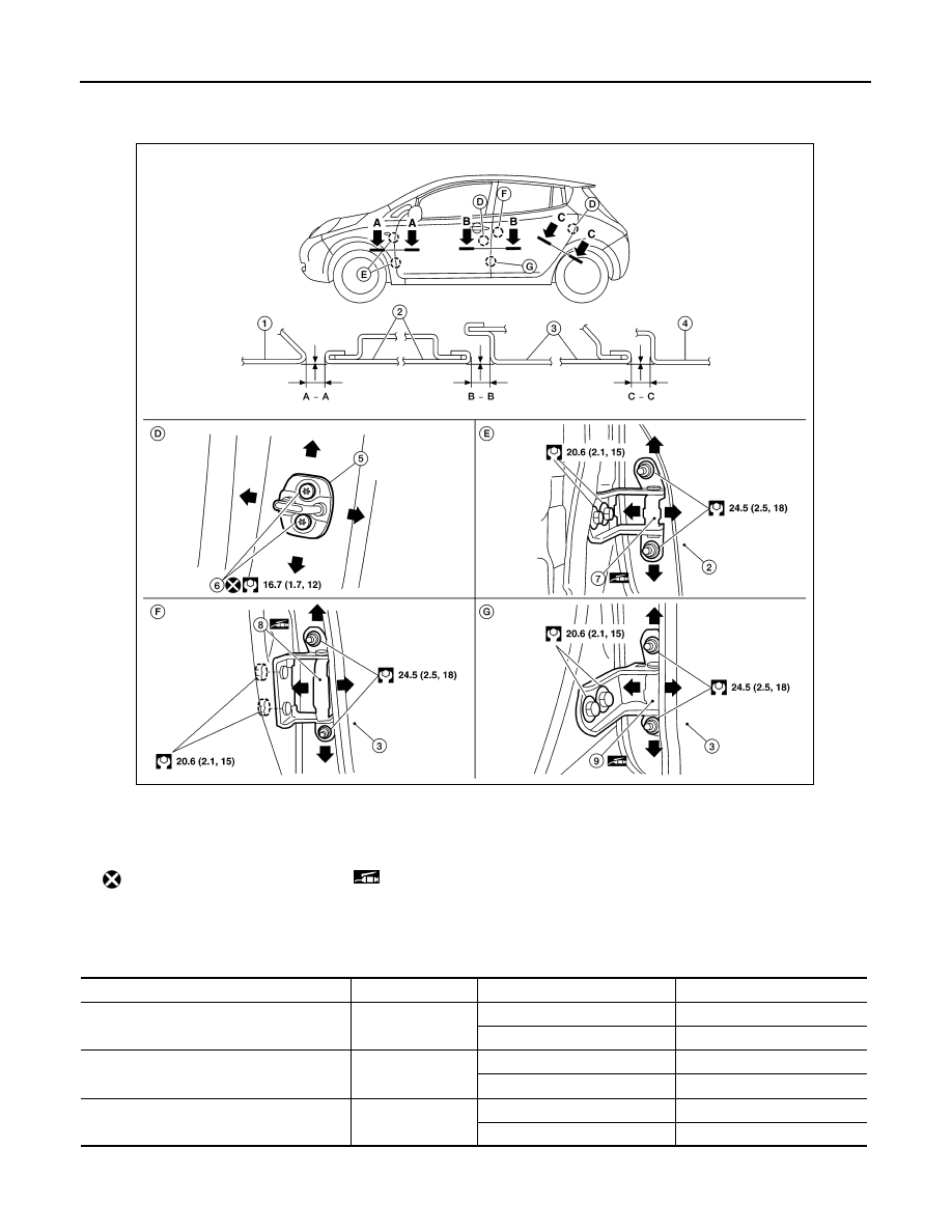
DOOR ASSEMBLY : Adjustment
INFOID:0000000010119867
Check the clearance and surface height between front door and each part by visual inspection and tactile feel.
If the clearance and the surface height are out of specification, adjust them according to the adjustment proce-
dure.
Unit: mm (in)
FITTING ADJUSTMENT PROCEDURE
1.
Front fender
2.
Front door
3.
Rear door
4.
Body side outer
5.
Door striker
6.
Bolt
7.
Front door hinge
8.
Rear door hinge (upper)
9.
Rear door hinge (lower)
Do not reuse
Grease
Portion
Section
Measurement
Standard
Front fender – Front door
A – A
Clearance
4.0
± 1.0 (0.16 ± 0.04)
Surface height
0.0
± 1.0 (0.00 ± 0.04)
Front door – Rear door
B – B
Clearance
4.2
± 1.0 (0.17 ± 0.04)
Surface height
0.0
± 1.0 (0.00 ± 0.04)
Front door – Rear door
C – C
Clearance
4.0
± 1.0 (0.16 ± 0.04)
Surface height
0.0
± 1.0 (0.00 ± 0.04)
AWKIA2364ZZ

FRONT DOOR
DLK-173
< REMOVAL AND INSTALLATION >
C
D
E
F
G
H
I
J
L
M
A
B
DLK
N
O
P
1. Remove front fender. Refer to
DLK-168, "Removal and Installation"
2. Loosen door hinge nuts (door side).
3. Adjust the surface height of front door according to the specifications provided.
4. Temporarily tighten door hinge nuts (door side).
5. Loosen door hinge bolts (body side).
6. Raise front door at rear end to adjust clearance of the front door according to the specifications provided.
7. Tighten bolts and nuts to the specified torque.
CAUTION:
• After installation, apply touch-up paint (body color) to the head of door hinge bolts and nuts.
• Check door hinge rotating part for poor lubrication. If necessary, apply a suitable multi-purpose
grease.
8. Install front fender. Refer to refer to
DLK-168, "Removal and Installation"
.
DOOR STRIKER ADJUSTMENT
Adjust door striker so that it becomes parallel with door lock insertion direction.
DOOR STRIKER
DOOR STRIKER : Removal and Installation
INFOID:0000000010119868
REMOVAL
Remove the door striker bolts and door striker.
INSTALLATION
Installation is in the reverse order of removal.
CAUTION:
• Do not reuse door striker bolts.
• After installation, perform the front door adjustment procedure. Refer to
• After installation, apply touch-up paint (body color) to the head of the door striker bolts.
DOOR HINGE
DOOR HINGE : Removal and Installation
INFOID:0000000010119869
WARNING:
Before servicing, push power switch OFF, disconnect 12V battery negative terminal and wait 5 min-
utes or more. Refer to
DLK-10, "Precaution for Removing 12V Battery"
CAUTION:
• Use two people when removing or installing the front door due to its heavy weight.
• When removing and installing front door assembly, support door using a suitable tool.
REMOVAL
1. Disconnect the negative and positive battery terminals and wait at least three minutes.
2. Remove front fender. Refer to
DLK-168, "Removal and Installation"
3. Remove front door assembly. Refer to
DLK-170, "DOOR ASSEMBLY : Removal and Installation"
.
4. Remove front door hinge mounting bolts (body side), and then remove front door hinge.
INSTALLATION
Note the following items, and install in the reverse order of removal.
CAUTION:
• Apply anticorrosive agent to the hinge mating surface.
• After installation, check front door open/close and lock/unlock operation. If necessary, perform the
front door adjustment procedure. Refer to
DLK-172, "DOOR ASSEMBLY : Adjustment"
.
• After installation, apply touch-up paint (body color) to the head of the door hinge nuts.

DLK-174
< REMOVAL AND INSTALLATION >
FRONT DOOR
• Check door hinge rotating part for poor lubrication. If neces-
sary, apply a suitable multi-purpose grease.
DOOR CHECK LINK
DOOR CHECK LINK : Removal and Installation
INFOID:0000000010119870
REMOVAL
1. Fully close the front door window.
2. Remove front door speaker. Refer to
AV-70, "Removal and Installation"
(DISPLAY AUDIO),
(NAVIGATION WITHOUT BOSE) or
AV-490, "Removal and Installation"
(NAV-
IGATION WITH BOSE).
3. Remove sealing screen.
NOTE:
Cut the butyl-tape so that some parts of the butyl-tape do not remain on the sealing screen, if the sealing
screen is reused.
4. Remove the door check link bolt (body side).
5. Remove the door check link bolts (door side).
6. Remove door check link (1) from door panel (2).
INSTALLATION
Installation is in the reverse order of removal.
CAUTION:
• Check front door open/close operation after installation.
• Check door check link rotating part for poor lubrication. If
necessary, apply a suitable multi-purpose grease.
: Grease point
JMKIA6553ZZ
JMKIA6413ZZ
: Grease point
JMKIA6554ZZ
Нет комментариевНе стесняйтесь поделиться с нами вашим ценным мнением.
Текст