Nissan Maxima. Manual — part 152
AV-428
< DTC/CIRCUIT DIAGNOSIS >
[COLOR DISPLAY - W/ BOSE]
SOUND SIGNAL CIRCUIT
YES
>> Replace AV control unit. Refer to
AV-481, "Removal and Installation"
.
NO
>> Replace satellite radio tuner. Refer to
AV-494, "Removal and Installation"
RIGHT CHANNEL
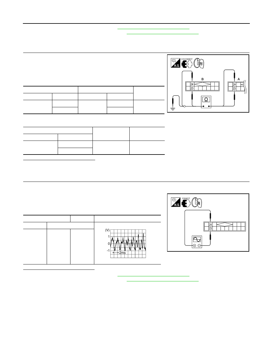
1.
CHECK HARNESS
1. Turn ignition switch OFF.
2. Disconnect satellite radio tuner (factory installed) connector
B111 and AV control unit connector M153.
3. Check continuity between satellite radio tuner (factory installed)
B111 (A) and AV control unit M153 (B).
4. Check continuity between satellite radio tuner (factory installed) connector B111 (A) and ground.
Are continuity results as specified?
YES
>> GO TO 2.
NO
>> Repair harness or connector.
2.
CHECK RIGHT CHANNEL AUDIO SIGNAL
1. Connect satellite radio tuner (factory installed) and AV control unit.
2. Turn ignition switch ON.
3. Check signal between satellite radio tuner (factory installed)
connector B111 terminals 23 and 24 with CONSULT or oscillo-
scope.
Are voltage readings as specified?
YES
>> Replace AV control unit. Refer to
AV-481, "Removal and Installation"
.
NO
>> Replace satellite radio tuner. Refer to
AV-494, "Removal and Installation"
A
B
Continuity
Connector
Terminal
Connector
Terminal
B111
23
M153
23
Yes
24
24
A
—
Continuity
Connector
Terminal
B111
23
Ground
No
24
ALNIA0338GB
(+)
(-)
Reference signal
Connector
Terminal
B111
24
23
ALNIA0881GB
SKIB3609E
AV
MICROPHONE SIGNAL CIRCUIT
AV-429
< DTC/CIRCUIT DIAGNOSIS >
[COLOR DISPLAY - W/ BOSE]
C
D
E
F
G
H
I
J
K
L
M
B
A
O
P
MICROPHONE SIGNAL CIRCUIT
Description
INFOID:0000000009471382
Voice signals are transmitted from the microphone to the Bluetooth
®
control unit using the microphone signal
circuits.
Diagnosis Procedure
INFOID:0000000009471383
Regarding Wiring Diagram information, refer to
AV-449, "Wiring Diagram - With BOSE Audio system Without
1.
CHECK HARNESS BETWEEN BLUETOOTH
®
CONTROL UNIT AND MICROPHONE
1. Turn ignition switch OFF.
2. Disconnect Bluetooth
®
control unit connector and microphone
connector.
3. Check continuity between Bluetooth
®
control unit harness con-
nector B131 (A) and microphone harness connector R7 (B).
4. Check continuity between Bluetooth
®
control unit harness connector B131 (A) and ground.
Are the continuity test results as specified?
YES
>> GO TO 2.
NO
>> Repair harness or connector.
2.
CHECK MICROPHONE POWER SUPPLY
1. Connect Bluetooth
®
control unit connector and microphone con-
nector.
2. Turn ignition switch ON.
3. Check voltage between microphone harness connector R7 ter-
minal 4 and ground.
Is voltage reading approx. 5 volts?
YES
>> GO TO 3.
NO
>> Replace Bluetooth
®
control unit. Refer to
AV-503, "Removal and Installation"
3.
CHECK MICROPHONE SIGNAL
A
B
Continuity
Connector
Terminal
Connector
Terminal
B131
7
R7
1
Yes
8
2
29
4
A
—
Continuity
Connector
Terminal
B131
7
Ground
No
8
29
WKIA5795E
(+)
(-)
Voltage (Approx.)
Connector
Terminal
R7
4
Ground
5V
WKIA5796E
AV-430
< DTC/CIRCUIT DIAGNOSIS >
[COLOR DISPLAY - W/ BOSE]
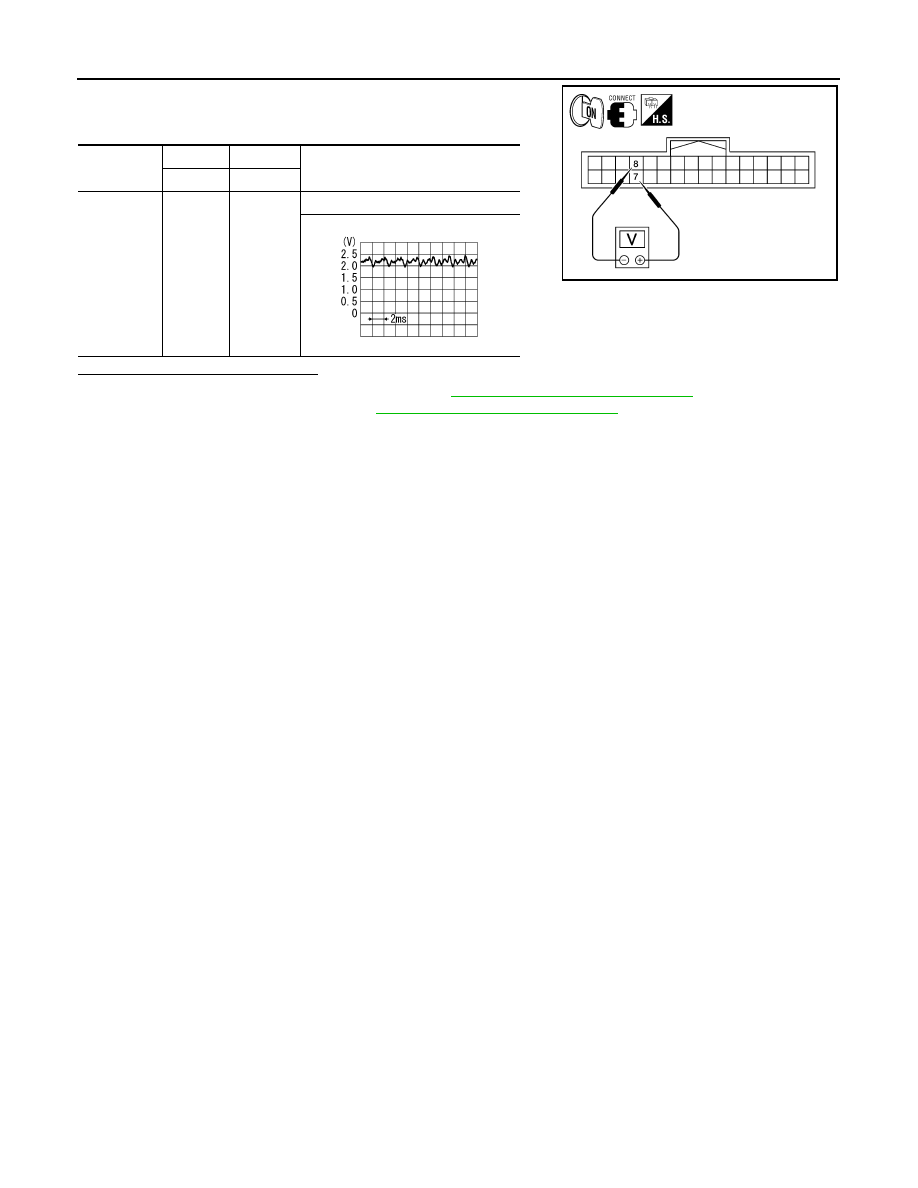
MICROPHONE SIGNAL CIRCUIT
Check signal between Bluetooth
®
control unit harness connector
B131 terminals 7 and 8.
Are voltage readings as specified?
YES
>> Replace Bluetooth
®
control unit. Refer to
AV-503, "Removal and Installation"
NO
>> Replace microphone. Refer to
AV-501, "Removal and Installation"
.
Connector
(+)
(-)
Reference signal
Terminal
Terminal
B131
7
8
While talking into microphone
ALNIA0934GB
PKIB5037J
AV
AV CONTROL UNIT
AV-431
< ECU DIAGNOSIS INFORMATION >
[COLOR DISPLAY - W/ BOSE]
C
D
E
F
G
H
I
J
K
L
M
B
A
O
P
ECU DIAGNOSIS INFORMATION
AV CONTROL UNIT
Reference Value
INFOID:0000000009471384
VALUES ON THE DIAGNOSIS TOOL
CONSULT data monitor item
TERMINAL LAYOUT
PHYSICAL VALUES
Display Item
Dis-
play
Vehicle status
Remarks
VHCL SPD SIG
ON
Vehicle speed >0 km/h (0 MPH)
Changes in indication may be delayed. This is nor-
mal.
OFF
Vehicle speed =0 km/h (0 MPH)
PKB SIG
ON
Parking brake is applied.
Changes in indication may be delayed. This is nor-
mal.
OFF
Parking brake is released.
ILLUM SIG
ON
Block the light beam from the auto
light optical sensor when the light SW
is ON .
—
OFF
Expose the auto light optical sensor
to light when the light SW is OFF or
ON.
IGN SIG
ON
Ignition switch ON
—
OFF
Ignition switch in ACC position
REV SIG
ON
Selector lever in R position
Changes in indication may be delayed. This is nor-
mal.
OFF
Selector lever in any position other
than R
AWNIA1971ZZ
Terminal
(Wire color)
Description
Condition
Reference value
(Approx.)
+
–
Signal name
Input/
Output
6
(W/G)
15
(L/B)
Steering switch signal A
Input
ON
Depress volume DOWN
switch.
0.7V
Depress volume UP switch.
1.3V
Depress
switch.
2.0V
Except for above.
3.3V
7
(V/Y)
Ground ACC power supply
Input
Ignition
switch
ACC
—
Battery voltage
9
(R/L)
Ground Illumination signal
Input
OFF
Lighting switch is OFF.
0V
Lighting switch is ON.
Battery voltage
Нет комментариевНе стесняйтесь поделиться с нами вашим ценным мнением.
Текст