Nissan Qashqai J11. Manual — part 2274

ENGINE MAINTENANCE (R9M)
MA-131
< PERIODIC MAINTENANCE >
C
D
E
F
G
H
I
J
K
L
M
B
MA
N
O
A
2.
Install oil filter (1) and O-ring (2) to oil filter body (3).
CAUTION:
Be sure to use a new O-ring.
• Securely press the oil filter into the oil filter body.
• When installing an O-ring, apply engine oil all around the O-
ring.
3.
Install oil filter body assembly to oil cooler.
OIL FILTER : Inspection
INFOID:0000000011497369
INSPECTION AFTER INSTALLATION
1.
Check that the engine oil level. Refer to
MA-128, "ENGINE OIL : Inspection"
2.
Start the engine, and check that there is no leak of engine oil.
3.
Stop the engine and wait for 10 minutes.
4.
Check that the engine oil level, and adjust the level. Refer to
MA-128, "ENGINE OIL : Inspection"
A
: Oil cooler side
E1BIA0600ZZ
Oil filter body:
25Nm (2.6 kg-m, 18 ft-lb)

MA-132
< PERIODIC MAINTENANCE >
CHASSIS MAINTENANCE
CHASSIS MAINTENANCE
HEADLAMP AIMING ADJUSTMENT (LED TYPE - LHD)
HEADLAMP AIMING ADJUSTMENT (LED TYPE - LHD) : Aiming Adjustment Proce-
dure
INFOID:0000000011497329
1.
Place the screen.
NOTE:
• Stop the vehicle at the perpendicular angle to the wall.
• Set the screen so that it is perpendicular to a level load surface.
2.
Face the vehicle squarely toward the screen and make the distance between the headlamp center and
the screen 10 m (32.8 ft).
3.
Start the engine and illuminate the headlamp (LO).
NOTE:
Block light from the headlamp that is not being adjusted with a thick fabric or another object, so that it
does not reach the adjustment screen.
CAUTION:
Never cover lens surface with tape, etc. because it is made from plastic.
4.
Use the aiming adjustment screw to adjust the elbow point projected by the low beams on the screen, so
that it is within the aiming adjustment area.
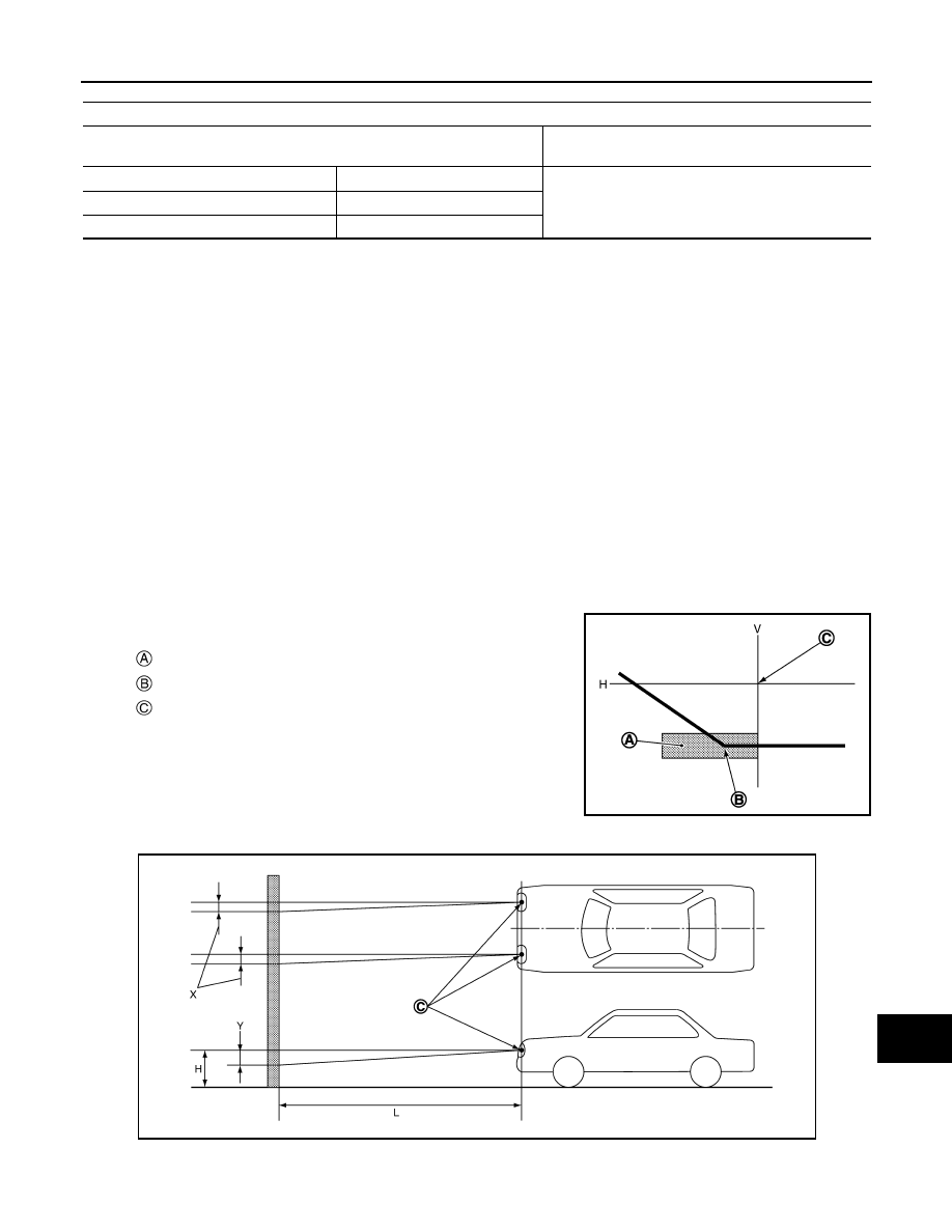
Low beam distribution on the screen
Aiming adjustment area
Elbow point
Headlamp center
H.
Horizontal center line of headlamp
V.
Vertical center line of headlamp
JSLIA0030ZZ
Vertical center line of headlamp H.
Horizontal center line of headlamp
L.
Distance from headlamp center to screen
X.
Aiming adjustment area
(Lateral)
Y.
Aiming adjustment area
(Vertical)
Distance from headlamp center to screen (L)
: 10 m (32.8 ft)
JSLIA0031ZZ
CHASSIS MAINTENANCE
MA-133
< PERIODIC MAINTENANCE >
C
D
E
F
G
H
I
J
K
L
M
B
MA
N
O
A
Unit: mm (in)
HEADLAMP AIMING ADJUSTMENT (LED TYPE - RHD)
HEADLAMP AIMING ADJUSTMENT (LED TYPE - RHD) : Aiming Adjustment Proce-
dure
INFOID:0000000011497330
1.
Place the screen.
NOTE:
• Stop the vehicle at the perpendicular angle to the wall.
• Set the screen so that it is perpendicular to a level load surface.
2.
Face the vehicle squarely toward the screen and make the distance between the headlamp center and
the screen 10 m (32.8 ft).
3.
Start the engine and illuminate the headlamp (LO).
NOTE:
Block light from the headlamp that is not being adjusted with a thick fabric or another object, so that it
does not reach the adjustment screen.
CAUTION:
Never cover lens surface with tape, etc. because it is made from plastic.
4.
Use the aiming adjustment screw to adjust the elbow point projected by the low beams on the screen, so
that it is within the aiming adjustment area.
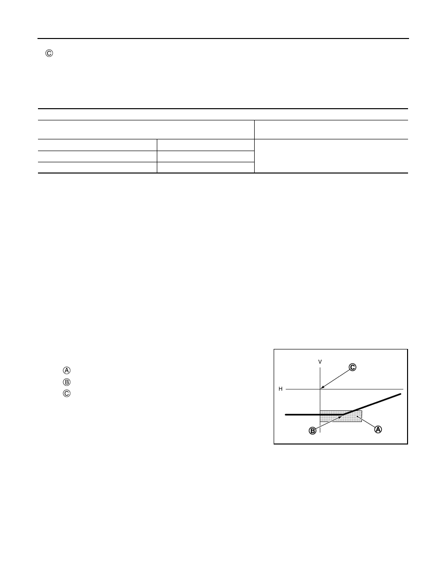
Low beam distribution on the screen
Aiming adjustment area
Vertical direction (Y)
(Lower side from headlamp center height)
Lateral direction (X)
(Right side from headlamp center line)
Highest light axis
100 (3.94)
0 - 100 (3.94)
Target light axis
100 (3.94)
Lowest light axis
130 (5.12)
Aiming adjustment area
Elbow point
Headlamp center
H.
Horizontal center line of headlamp
V.
Vertical center line of headlamp
JSLIA0028ZZ
JSLIA0029ZZ
MA-134
< PERIODIC MAINTENANCE >
CHASSIS MAINTENANCE
Unit: mm (in)
HEADLAMP AIMING ADJUSTMENT (HALOGEN TYPE - LHD)
HEADLAMP AIMING ADJUSTMENT (HALOGEN TYPE - LHD) : Aiming Adjustment
Procedure
INFOID:0000000011497334
1.
Place the screen.
NOTE:
• Stop the vehicle at the perpendicular angle to the wall.
• Set the screen so that it is perpendicular to a level load surface.
2.
Face the vehicle squarely toward the screen and make the distance between the headlamp center and
the screen 10 m (32.8 ft).
3.
Start the engine and illuminate the headlamp (LO).
NOTE:
Block light from the headlamp that is not being adjusted with a thick fabric or another object, so that it
does not reach the adjustment screen.
CAUTION:
Never cover lens surface with tape, etc. because it is made from plastic.
4.
Use the aiming adjustment screw to adjust the elbow point projected by the low beams on the screen, so
that it is within the aiming adjustment area.
Low beam distribution on the screen
Vertical center line of headlamp H.
Horizontal center line of headlamp
L.
Distance from headlamp center to screen
X.
Aiming adjustment area
(Lateral)
Y.
Aiming adjustment area
(Vertical)
Distance from headlamp center to screen (L)
: 10 m (32.8 ft)
Aiming adjustment area
Vertical direction (Y)
(Lower side from headlamp center height)
Lateral direction (X)
(Left side from headlamp center line)
Highest light axis
100 (3.94)
0 - 100 (3.94)
Target light axis
100 (3.94)
Lowest light axis
130 (5.12)
Aiming adjustment area
Elbow point
Headlamp center
H.
Horizontal center line of headlamp
V.
Vertical center line of headlamp
JSLIA0030ZZ
Нет комментариевНе стесняйтесь поделиться с нами вашим ценным мнением.
Текст