Nissan Qashqai J11. Manual — part 1710

LIGHT & RAIN SENSOR
EXL-141
< DTC/CIRCUIT DIAGNOSIS >
[LED HEADLAMP]
C
D
E
F
G
H
I
J
K
M
A
B
EXL
N
O
P
LIGHT & RAIN SENSOR
Component Function Check
INFOID:0000000010452494
1.
CHECK LIGHT & RAIN SENSOR
1.
Clean light & rain sensor detection area of windshield fully.
2.
Turn ignition switch ON.
3.
Turn lighting switch AUTO.
4.
With the light & rain sensor illuminating, check the auto light function.
Is the inspection result normal?
YES
>> Light & rain sensor is normal.
NO
>> Refer to
EXL-141, "Diagnosis Procedure"
.
Diagnosis Procedure
INFOID:0000000010452495
1.
CHECK LIGHT & RAIN SENSOR POWER SUPPLY
1.
Turn ignition switch OFF
2.
Disconnect light & rain sensor connector.
3.
Turn ignition switch ON.
4.
Check voltage between light & rain sensor harness connector and ground.
Is the inspection result normal?
YES
>> GO TO 3.
NO
>> GO TO 2.
2.
CHECK LIGHT & RAIN SENSOR POWER SUPPLY CIRCUIT
1.
Turn ignition switch OFF.
2.
Remove room lamp relay.
3.
Check continuity between room lamp relay harness connector and light & rain sensor harness connector.
Is the inspection result normal?
YES
>> Perform the interior room lamp power supply circuit diagnosis. Refer to
.
NO
>> Repair or replace harness.
3.
CHECK LIGHT & RAIN SENSOR GROUND CIRCUIT
Check continuity between light & rain sensor harness connector and ground.
Condition
Auto light function
Light & rain sensor
When illuminating
Not operating
When shutting off light
Operating
+
-
Voltage
Light & rain sensor
Connector
Terminal
R5
1
Ground Battery
voltage
Room lamp relay
Light & rain sensor
Continuity
Connector
Terminal
Connector
Terminal
M80
7
R5
1
Existed
Light & rain sensor
—
Continuity
Connector
Terminal
R5
3
Ground
Existed
EXL-142
< DTC/CIRCUIT DIAGNOSIS >
[LED HEADLAMP]
LIGHT & RAIN SENSOR
Is the inspection result normal?
YES
>> GO TO 4.
NO
>> Repair or replace harness.
4.
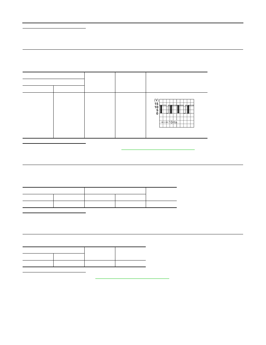
CHECK LIGHT & RAIN SENSOR SIGNAL
1.
Connect light & rain sensor connector.
2.
Turn ignition switch ON.
3.
Check voltage between BCM harness connector and ground.
Is the inspection result normal?
YES
>> Replace light & rain sensor. Refer to
EXL-171, "Removal and Installation"
NO
>> GO TO 5.
5.
CHECK LIGHT & RAIN SENSOR SIGNAL CIRCUIT (OPEN)
1.
Turn ignition switch OFF.
2.
Disconnect BCM connector and light & rain sensor connector.
3.
Check continuity between BCM harness connector and light & rain sensor harness connector.
Is the inspection result normal?
YES
>> GO TO 6.
NO
>> Repair or replace harness.
6.
CHECK LIGHT & RAIN SENSOR SIGNAL CIRCUIT (SHORT)
Check continuity between BCM harness connector and ground.
Is the inspection result normal?
YES
>> Replace BCM. Refer to
BCS-132, "Removal and Installation"
.
NO
>> Repair or replace harness.
+
-
Condition
Voltage
(Approx.)
BCM
Connector
Terminal
M70
47
Ground
Ignition switch
ON
8.7V
JPMIA0156GB
BCM
Light & rain sensor
Continuity
Connector
Terminal
Connector
Terminal
M70
47
R5
2
Existed
BCM
—
Continuity
Connector
Terminal
M70
47
Ground
Not existed

HAZARD SWITCH
EXL-143
< DTC/CIRCUIT DIAGNOSIS >
[LED HEADLAMP]
C
D
E
F
G
H
I
J
K
M
A
B
EXL
N
O
P
HAZARD SWITCH
Component Function Check
INFOID:0000000010338832
1.
CHECK HAZARD SWITCH SIGNAL
With CONSULT
1.
Turn ignition switch ON.
2.
Select “FLASHER” of “BCM” using CONSULT.
3.
Select “HAZARD SW” in “Data Monitor” mode.
4.
With operating the hazard switch, check the monitor status.
Is the inspection result normal?
YES
>> Hazard switch circuit is normal.
NO
>> Refer to
EXL-143, "Diagnosis Procedure"
.
Diagnosis Procedure
INFOID:0000000010338833
1.
CHECK HAZARD SWITCH SIGNAL
1.
Turn ignition switch OFF.
2.
Disconnect hazard switch connector.
3.
Check voltage between hazard switch connector and ground.
Is the inspection result normal?
YES
>> GO TO 4.
NO
>> GO TO 2.
2.
CHECK HAZARD SWITCH SIGNAL CIRCUIT (OPEN)
1.
Disconnect BCM connector.
2.
Check continuity between hazard switch harness connector and BCM harness connector.
Is the inspection result normal?
YES
>> GO TO 3.
NO
>> Repair or replace harness.
3.
CHECK HAZARD SWITCH SIGNAL CIRCUIT (SHORT)
Check continuity between hazard switch harness connector and ground.
Is the inspection result normal?
YES
>> Replace BCM. Refer to
BCS-132, "Removal and Installation"
.
Monitor item
Condition
Monitor status
HAZARD SW
Hazard switch
ON
On
OFF
Off
+
-
Voltage
Hazard switch
Connector
Terminal
M39
2
Ground
9 – 16 V
Hazard switch
BCM
Continuity
Connector
Terminal
Connector
Terminal
M39
2
M70
51
Existed
Hazard switch
—
Continuity
Connector
Terminal
M39
2
Ground
Not existed

EXL-144
< DTC/CIRCUIT DIAGNOSIS >
[LED HEADLAMP]
HAZARD SWITCH
NO
>> Repair or replace harness.
4.
CHECK HAZARD SWITCH GROUND CIRCUIT
Check continuity between hazard switch harness connector and ground.
Is the inspection result normal?
YES
>> GO TO 5.
NO
>> Repair or replace harness.
5.
CHECK HAZARD SWITCH
Check hazard switch. Refer to
EXL-144, "Component Inspection"
.
Is the inspection result normal?
YES
>> INSPECTION END
NO
>> Replace hazard switch. Refer to
EXL-168, "Removal and Installation"
Component Inspection
INFOID:0000000010452497
1.
CHECK HAZARD SWITCH
1.
Turn ignition switch OFF.
2.
Disconnect hazard switch connector.
3.
Check continuity of hazard switch terminals.
Is the inspection result normal?
YES
>> INSPECTION END
NO
>> Replace hazard switch. Refer to
EXL-168, "Removal and Installation"
Hazard switch
—
Continuity
Connector
Terminal
M39
1
Ground
Existed
Hazard switch
Condition
Continuity
Terminal
1
2
Hazard switch
ON
Existed
OFF
Not existed
Нет комментариевНе стесняйтесь поделиться с нами вашим ценным мнением.
Текст