Nissan Qashqai J11. Manual — part 986
STC-4
< PRECAUTION >
PRECAUTIONS
PRECAUTION
PRECAUTIONS
Precaution for Supplemental Restraint System (SRS) "AIR BAG" and "SEAT BELT
PRE-TENSIONER"
INFOID:0000000010452181
The Supplemental Restraint System such as “AIR BAG” and “SEAT BELT PRE-TENSIONER”, used along
with a front seat belt, helps to reduce the risk or severity of injury to the driver and front passenger for certain
types of collision. Information necessary to service the system safely is included in the “SRS AIR BAG” and
“SEAT BELT” of this Service Manual.
WARNING:
Always observe the following items for preventing accidental activation.
• To avoid rendering the SRS inoperative, which could increase the risk of personal injury or death in
the event of a collision that would result in air bag inflation, all maintenance must be performed by
an authorized NISSAN/INFINITI dealer.
• Improper maintenance, including incorrect removal and installation of the SRS, can lead to personal
injury caused by unintentional activation of the system. For removal of Spiral Cable and Air Bag
Module, see “SRS AIR BAG”.
• Never use electrical test equipment on any circuit related to the SRS unless instructed to in this Ser-
vice Manual. SRS wiring harnesses can be identified by yellow and/or orange harnesses or harness
connectors.
PRECAUTIONS WHEN USING POWER TOOLS (AIR OR ELECTRIC) AND HAMMERS
WARNING:
Always observe the following items for preventing accidental activation.
• When working near the Air Bag Diagnosis Sensor Unit or other Air Bag System sensors with the
ignition ON or engine running, never use air or electric power tools or strike near the sensor(s) with
a hammer. Heavy vibration could activate the sensor(s) and deploy the air bag(s), possibly causing
serious injury.
• When using air or electric power tools or hammers, always switch the ignition OFF, disconnect the
battery, and wait at least 3 minutes before performing any service.
Precaution Necessary for Steering Wheel Rotation After Battery Disconnect
INFOID:0000000010495410
CAUTION:
Comply with the following cautions to prevent any error and malfunction.
• Before removing and installing any control units, first turn the ignition power source and accessory
power source to the OFF, then disconnect both battery cables.
• After finishing work, confirm that all control unit connectors are connected properly, then re-connect
both battery cables.
• Always use CONSULT to perform self-diagnosis as a part of each function inspection after finishing
work. If a DTC is detected, perform trouble diagnosis according to self-diagnosis results.
For vehicle with steering lock unit, if the battery is disconnected or discharged, the steering wheel will lock and
cannot be turned.
If turning the steering wheel is required with the battery disconnected or discharged, follow the operation pro-
cedure below before starting the repair operation.
OPERATION PROCEDURE
1.
Connect both battery cables.
NOTE:
Supply power using jumper cables if battery is discharged.
2.
Open driver door.
3.
Turn the ignition switch to the ON position.
(At this time, the steering lock will be released.)
4.
Turn the ignition switch to OFF position with driver door open.
5.
Wait for 3 minutes or longer with driver door open.
NOTE:
• Do not close driver door because the steering wheel locks when driver door is closed.
PRECAUTIONS
STC-5
< PRECAUTION >
C
D
E
F
H
I
J
K
L
M
A
B
STC
N
O
P
• The auto acc function is adapted to this vehicle. For this reason, even when the ignition switch is turned
to OFF position, the accessory power source does not turned OFF and continues to be supplied for a
certain amount of time.
6.
Disconnect both battery cables. The steering lock will remain released with both battery cables discon-
nected and the steering wheel can be turned.
7.
Perform the necessary repair operation.
8.
When the repair work is completed, re-connect both battery cables. With the brake pedal released, turn
the ignition switch from OFF position to ON position, then to LOCK position. (The steering wheel will lock
when the ignition switch is turned to LOCK position.)
9.
Perform self-diagnosis check of all control units using CONSULT.
Precautions for Removing Battery Terminal
INFOID:0000000010503405
• With the adoption of Auto ACC function, ACC power is automatically supplied by operating the intelligent key
or remote keyless entry or by opening/closing the driver side door. In addition, ACC power is supplied even
after the ignition switch is turned to the OFF position, i.e. ACC power is supplied for a certain fixed time.
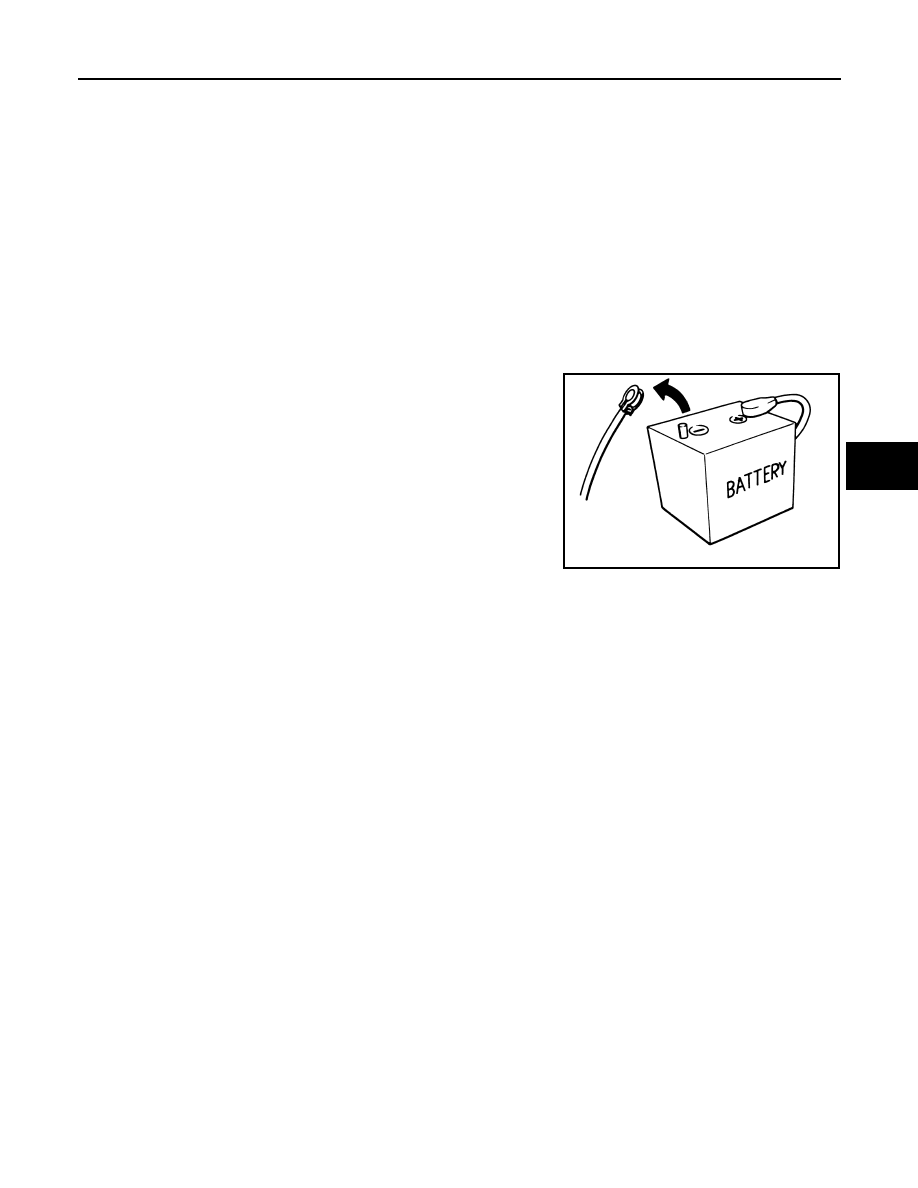
• When disconnecting the 12V battery terminal, turn off the ACC
power before disconnecting the 12V battery terminal, observing
“How to disconnect 12V battery terminal” described below.
NOTE:
Some ECUs operate for a certain fixed time even after ignition
switch is turned OFF and ignition power supply is stopped. If the
battery terminal is disconnected before ECU stops, accidental DTC
detection or ECU data damage may occur.
• For vehicles with the 2-batteries, be sure to connect the main bat-
tery and the sub battery before turning ON the ignition switch.
NOTE:
If the ignition switch is turned ON with any one of the terminals of
main battery and sub battery disconnected, then DTC may be detected.
• After installing the 12V battery, always check "Self Diagnosis Result" of all ECUs and erase DTC.
NOTE:
The removal of 12V battery may cause a DTC detection error.
HOW TO DISCONNECT 12V BATTERY TERMINAL
Disconnect 12V battery terminal according to instruction described below.
1.
Open the hood.
2.
Turn ignition switch to the ON position.
3.
Turn ignition switch to the OFF position with the driver side door opened.
4.
Get out of the vehicle and close the driver side door.
5.
Wait at least 3 minutes. For vehicle with the engine listed below, remove the battery terminal after a lapse
of the specified time.
CAUTION:
While waiting, never operate the vehicle such as locking, opening, and closing doors. Violation of
this caution results in the activation of ACC power supply according to the Auto ACC function.
6.
Remove 12V battery terminal.
CAUTION:
After installing 12V battery, always check self-diagnosis results of all ECUs and erase DTC.
Precaution for Stop/Start System Service
INFOID:0000000010452184
CAUTION:
When performing an inspection and its related work with the engine at idle, always open the hood and
release the stop/start system.
SEF289H
D4D engine
: 20 minutes
HRA2DDT
: 12 minutes
K9K engine
: 4 minutes
M9R engine
: 4 minutes
R9M engine
: 4 minutes
V9X engine
: 4 minutes

STC-6
< PRECAUTION >
PRECAUTIONS
Service Notice and Precautions for EPS System
INFOID:0000000010452185
• Check the following item when performing the trouble diagnosis.
- Check any possible causes by interviewing the symptom and it
′
s condition from the customer if any malfunc-
tion, such as power steering warning lamp is turned ON, occurs.
- Check if air pressure and size of tires are proper, the specified part is used for the steering wheel, and con-
trol unit is genuine part.
- Check if the connection of steering column assembly and steering gear assembly is proper (there is not
looseness of mounting bolts, damage of rods, boots or sealants, and leakage of grease, etc.).
- Check if the wheel alignment is adjusted properly.
- Check if there is any damage or modification to suspension or body resulting in increased weight or altered
ground clearance.
- Check if installation conditions of each link and suspension are proper.
- Check if the battery voltage is proper.
- Check connection conditions of each connector are proper.
- Before connecting or disconnecting the EPS control unit harness
connector, turn ignition switch “OFF” and disconnect battery
ground cable. Because battery voltage is applied to EPS control
unit even if ignition switch is turned “OFF”.
- When connecting or disconnecting pin connectors into or from
EPS control unit, take care not to damage pin terminals (bend or
break).
- When connecting pin connectors, make sure that there are no
bends or breaks on EPS control unit pin terminal.
• During quick steering, rasping noise may be heard from around the
steering wheel. This is not a malfunction. The noise is an operating
noise of the EPS system under normal conditions. If the rasping
noise occurs during slow steering, this may not be an operating
noise of the system. In this case, it is necessary to find out the
location of the noise and repair, if necessary.
SEF289H
SEF291H
COMPONENT PARTS
STC-7
< SYSTEM DESCRIPTION >
C
D
E
F
H
I
J
K
L
M
A
B
STC
N
O
P
SYSTEM DESCRIPTION
COMPONENT PARTS
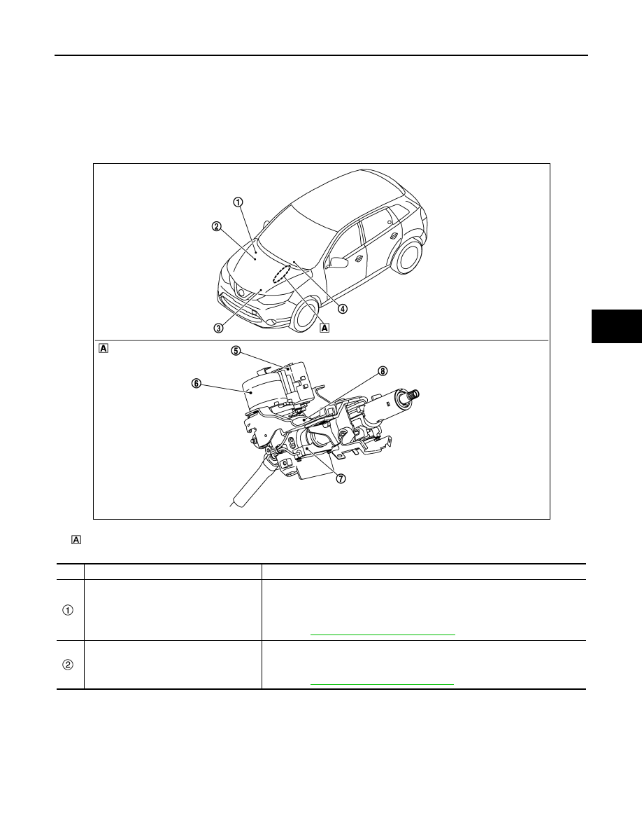
Component Parts Location
INFOID:0000000010452096
LHD MODELS
Steering column assembly
No.
Component
Function
Around view monitor control unit
• Transmits mainly the following signals to EPS control unit via CAN communica-
tion.
- Intelligent parking assist status signal
- Current command signal
• Refer to
AV-131, "Component Parts Location"
for detailed installation location.
ABS actuator and electric unit (control unit)
• Transmits mainly the following signal to EPS control unit via CAN communica-
tion.
- Vehicle speed signal
• Refer to
BRC-9, "Component Parts Location"
for detailed installation location.
JMGIA0186ZZ
Нет комментариевНе стесняйтесь поделиться с нами вашим ценным мнением.
Текст