Nissan Qashqai J11. Manual — part 818

DLN-188
< REMOVAL AND INSTALLATION >
[REAR PROPELLER SHAFT: C-CVJ-C]
REAR PROPELLER SHAFT
8.
Remove propeller shaft assembly fixing nuts, and separate pro-
peller shaft assembly from electric controlled coupling of final
drive.
9.
Remove center bearing mounting bracket mounting nuts.
10. Remove propeller shaft assembly.
11. Remove clips and then remove center bearing mounting bracket
(upper/lower).
12. Perform inspection after removal. Refer to
INSTALLATION
Note the following, and install in the reverse order of removal.
• For non-reusable parts, refer to
• For each tightening torque, refer to
.
• After removing propeller shaft, replace stud bolts on electric controlled coupling. Refer to
.
• Remove any moisture, oil, or foreign material from matching surface on transfer companion flange, electric
controlled coupling and propeller shaft flange.
• Install center bearing mounting bracket (upper) with its arrow mark
facing forward.
• Adjust position of center bearing mounting bracket (upper)
, cen-
ter bearing mounting bracket (lower)
sliding back and forth to
prevent play in thrust direction of center bearing insulator
. Install
center bearing mounting bracket (upper/lower) to vehicle.
• Center bearing mounting bracket fixing nuts must be tightened in
the order from left to right.
JSDIA5330ZZ
JSDIA4492ZZ
JSDIA4491ZZ
JSDIA5331ZZ
REAR PROPELLER SHAFT
DLN-189
< REMOVAL AND INSTALLATION >
[REAR PROPELLER SHAFT: C-CVJ-C]
C
E
F
G
H
I
J
K
L
M
A
B
DLN
N
O
P
• Align matching marks
to install propeller shaft flange yoke and
electric controlled coupling of final drive.
• Align matching marks
to install propeller shaft flange yoke and
transfer companion flange.
• If propeller shaft assembly, final drive assembly or electric controlled coupling has been replaced, connect
propeller shaft assembly and electric controlled coupling of final drive as follows:
- Install propeller shaft
while aligning its matching mark
of pro-
peller shaft with matching mark
on stud bolt of electric controlled
coupling
as close as possible.
CAUTION:
When replaced stud bolt, use the painted matching mark in
removal as a guide.
• Perform inspection after installation. Refer to
Inspection
INFOID:0000000010763748
INSPECTION AFTER REMOVAL
Appearance
Check propeller shaft tube surface for dents or cracks. If malfunction is detected, replace propeller shaft
assembly.
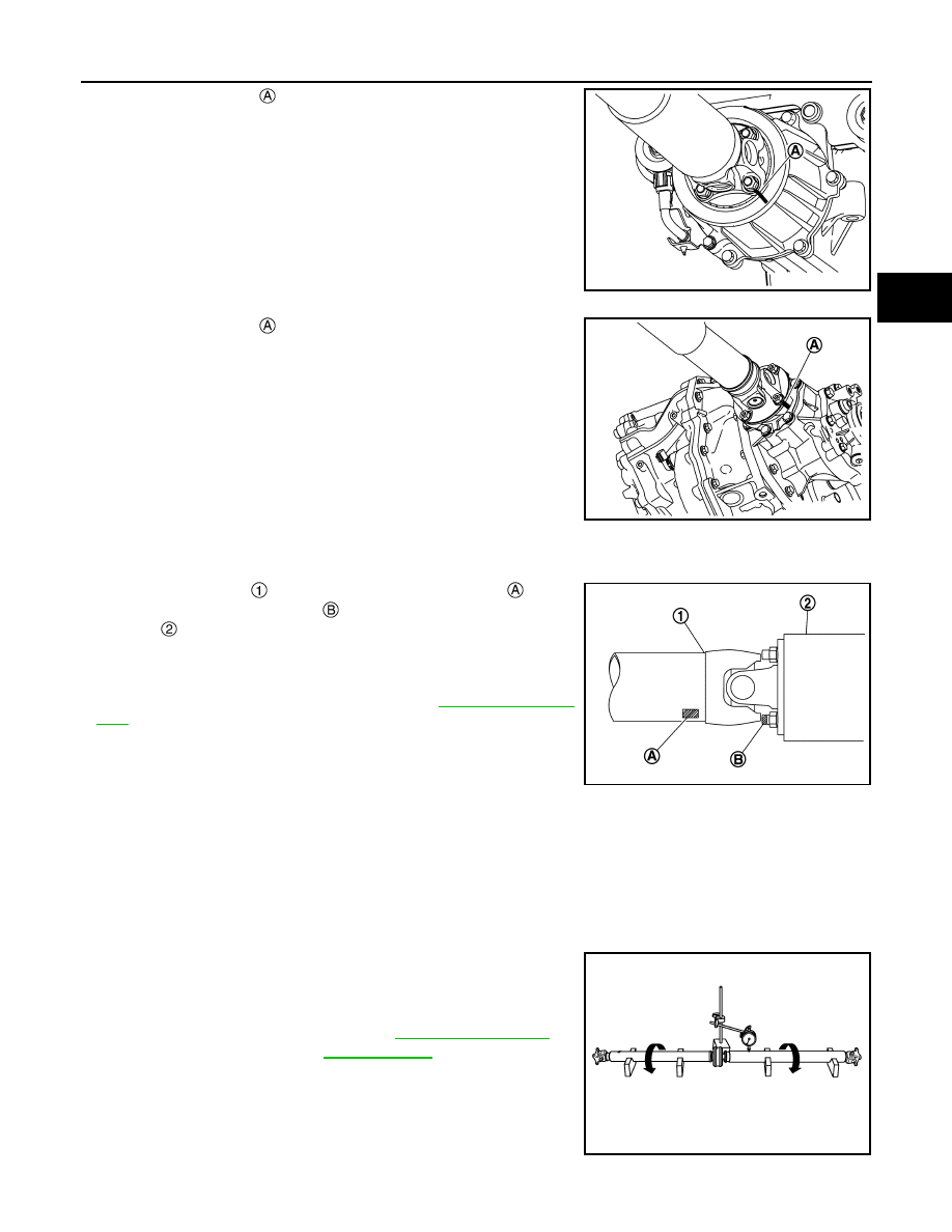
Propeller Shaft Runout
Check propeller shaft runout at measuring points with a dial indica-
tor. If runout exceeds specifications, replace propeller shaft assem-
bly.
JSDIA5325ZZ
JSDIA5328ZZ
JSDIA5332ZZ
Propeller shaft runout
: Refer to
.
JSDIA0193ZZ

DLN-190
< REMOVAL AND INSTALLATION >
[REAR PROPELLER SHAFT: C-CVJ-C]
REAR PROPELLER SHAFT
• Propeller shaft runout measuring point (Point “ ”).
Journal Axial Play
As shown in the figure, while fixing yoke on one side, check axial
play of joint. If it is outside the standard, replace propeller shaft
assembly.
CAUTION:
Never disassemble joints.
Center Bearing
Check center bearing for noise and damage. If malfunction is detected, replace propeller shaft assembly.
CAUTION:
Never disassemble center bearing.
INSPECTION AFTER INSTALLATION
After assembly, perform a driving test to check propeller shaft vibration. If vibration occurred, separate propel-
ler shaft from final drive. Reinstall propeller shaft by changing the phase between electric controlled coupling
stud bolt and propeller shaft by the one bolt hole at a time. Then perform driving test and check propeller shaft
vibration again at each point.
: Front side
Dimension
MR20DD models
A
: 533.5 mm (21.00 in)
B
: 492.0 mm (19.37 in)
R9M models
A
: 541.5 mm (21.32 in)
B
: 488.7 mm (19.24 in)
JPDID0001ZZ
Journal axial play
: Refer to
.
PDA0005D

SERVICE DATA AND SPECIFICATIONS (SDS)
DLN-191
< SERVICE DATA AND SPECIFICATIONS (SDS)
[REAR PROPELLER SHAFT: C-CVJ-C]
C
E
F
G
H
I
J
K
L
M
A
B
DLN
N
O
P
SERVICE DATA AND SPECIFICATIONS (SDS)
SERVICE DATA AND SPECIFICATIONS (SDS)
General Specifications
INFOID:0000000010763749
MR20DD and R9M MODELS
Propeller Shaft Runout
INFOID:0000000010763750
Unit: mm (in)
Journal Axial Play
INFOID:0000000010763751
Unit: mm (in)
Applied model
Axle
4WD
Transaxle
CVT and MT
Propeller shaft model
C-CVJ-C
Number of joints
3
Joint type
1st joint
Universal (Shell type)
2nd joint
CVJ type
3rd joint
Universal (Shell type)
Coupling method
Transfer side
Flange type
Rear final drive side
Flange type
Shaft length
1st (Spider to CVJ joint center)
1182 mm (46.54 in)
2nd (CVJ joint center to spider)
983 mm (38.70 in)
Shaft outer diameter
1st shaft
63.5 mm (2.500 in)
2nd shaft
70.0 mm (2.756 in)
Item
Standard
Propeller shaft runout
0.6 (0.024) or less
Item
Standard
Journal axial play
0 (0)
Нет комментариевНе стесняйтесь поделиться с нами вашим ценным мнением.
Текст