Nissan Qashqai J11. Manual — part 774
DLN-12
< SYSTEM DESCRIPTION >
[TRANSFER: TY21C]
COMPONENT PARTS
4WD Control Unit
INFOID:0000000010755225
• Controls driving force distribution by signals from each sensor from front wheel driving mode (100:0) to 4-
wheel driving mode (50:50).
• Fail-safe mode is available if malfunction is detected in 4WD system. For fail-safe, refer to
.
4WD ACTUATOR RELAY
4WD actuator relay is integrated with 4WD control unit, and supplies 4WD solenoid with voltage.
Electric Controlled Coupling
INFOID:0000000010755226
Electric controlled coupling is integrated with rear final drive and transmits driving force to rear final drive. For
operation, refer to
DLN-13, "Operation Description"
.
4WD Solenoid
INFOID:0000000010755227
• 4WD solenoid is integrated with electric controlled coupling.
• Controls electric controlled coupling by command current from 4WD control unit.
4WD Mode Switch
INFOID:0000000010755228
4WD mode is selectable among 2WD mode, AUTO mode, and LOCK mode by operating the 4WD mode
switch while the engine is running.
ABS actuator and electric unit (con-
trol unit)
Mainly transmits the following signals to 4WD control unit via CAN communication.
• Each wheel speed signal
• Decel G sensor signal
• Side G sensor signal
• Yaw rate sensor signal
For detailed installation location, refer to
BRC-8, "Component Parts Location"
148, "Component Parts Location"
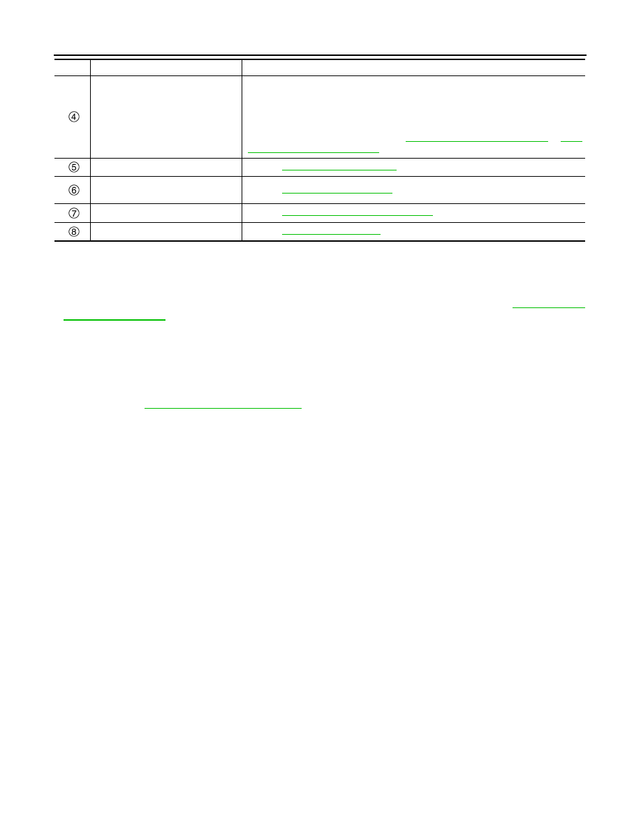
4WD mode switch
Refer to
.
4WD control unit
• 4WD actuator relay
Refer to
.
Electric controlled coupling
Refer to
DLN-12, "Electric Controlled Coupling"
.
4WD solenoid
Refer to
No.
Component
Function

STRUCTURE AND OPERATION
DLN-13
< SYSTEM DESCRIPTION >
[TRANSFER: TY21C]
C
E
F
G
H
I
J
K
L
M
A
B
DLN
N
O
P
STRUCTURE AND OPERATION
Sectional View
INFOID:0000000010755229
Operation Description
INFOID:0000000010755230
POWER TRANSFER DIAGRAM
1.
Transfer cover
2.
Transfer case
3.
Ring gear bearing (transfer case side)
4.
Ring gear shaft
5.
Pinion bearing
6.
Drive pinion
7.
Companion flange
8.
Ring gear
9.
Ring gear bearing (transfer cover
side)
JSDIA3966ZZ

DLN-14
< SYSTEM DESCRIPTION >
[TRANSFER: TY21C]
STRUCTURE AND OPERATION
ELECTRIC CONTROLLED COUPLING
1.
The 4WD control unit supplies command current to electric con-
trolled coupling (4WD solenoid).
2.
The control clutch is engaged by electromagnet and torque is
detected in control clutch.
3.
The cam operates in response to control clutch torque and
applies pressure to main clutch.
4.
The main clutch transmits torque to front wheels according to
pressing power.
• Transmission torque to the rear wheels is determined accord-
ing to command current.
Engine
Transaxle
Transfer
Propeller shaft
Electric controlled coupling
Rear final drive
JSDIA0961ZZ
JSDIA0972GB
SDIA1844E
SYSTEM
DLN-15
< SYSTEM DESCRIPTION >
[TRANSFER: TY21C]
C
E
F
G
H
I
J
K
L
M
A
B
DLN
N
O
P
SYSTEM
4WD SYSTEM
4WD SYSTEM : System Description
INFOID:0000000010755231
• Pressing force of multiple disc clutch is controlled by electric control. Driving torque distribution of front and
rear wheels changes automatically between approximately 100 : 0 (2WD) and 50 : 50 (4WD) to have an opti-
mized torque distribution adapted to road condition change.
• Driving mode is selectable among 2WD mode, AUTO mode, and LOCK mode by operating the 4WD mode
switch.
• In accordance with fail-safe function, when system is malfunctioning, 4WD control stops, and the system
becomes 2WD or slight 4WD (rear-wheels still have some driving torque). Refer to
.
• When a high load status continues for electric controlled coupling, 4WD control temporarily becomes front
wheel drive, according to protection function. Refer to
DLN-18, "4WD SYSTEM : Protection Function"
.
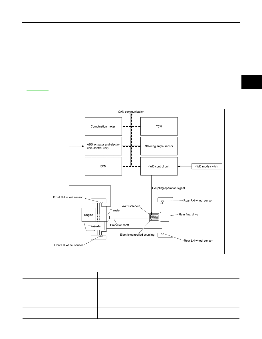
SYSTEM DIAGRAM
Signal with Communication Line
Major signal transmission between each unit via CAN communication lines are shown in the following table.
JSDIA6026GB
Component parts
Signal item
Combination meter
Mainly transmits the following signals to 4WD control unit via CAN communication.
• Parking brake switch signal
Mainly receives the following signals from 4WD control unit via CAN communication.
• 4WD warning lamp signal
• 4WD mode indicator lamp signal
• Torque distribution indicator signal
Steering angle sensor
Mainly transmits the following signals to 4WD control unit via CAN communication.
• steering angle sensor signal
Нет комментариевНе стесняйтесь поделиться с нами вашим ценным мнением.
Текст