Nissan Qashqai J11. Manual — part 2138

AV
STEERING SWITCH
AV-241
< DTC/CIRCUIT DIAGNOSIS >
[NAVIGATION]
C
D
E
F
G
H
I
J
K
L
M
B
A
O
P
STEERING SWITCH
Diagnosis Procedure
INFOID:0000000010435734
Regarding Wiring Diagram information, refer to
.
1.
CHECK STEERING WHEEL AUDIO CONTROL SWITCH RESISTANCE
1.
Turn ignition switch OFF.
2.
Disconnect combination switch connector M66.
3.
Check resistance between the terminals of combination switch connector M66.
Is the inspection result normal?
YES
>> GO TO 2.
NO
>> Replace steering switches. Refer to
AV-261, "Removal and Installation"
.
2.
CHECK HARNESS BETWEEN COMBINATION METER AND COMBINATION SWITCH
1.
Disconnect combination meter connector M51 and combination switch connector M66.
2.
Check continuity between combination meter connector M51 and combination switch connector M66.
3.
Check continuity between combination meter connector M51 and ground.
Is the inspection result normal?
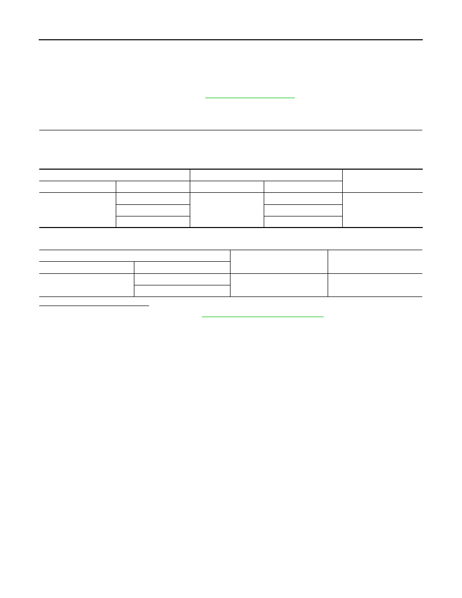
Combination switch connector M66
Condition
Resistance
Ω
(Approx.)
Terminal
Terminal
29
23
Depress SOURCE switch.
1
Depress
switch.
121
Depress
switch.
321
Depress
switch.
723
Depress ENTER switch.
2023
24
Depress
switch.
1
Depress
switch.
121
Depress
switch.
321
Depress
switch.
723
Depress DISPLAY switch.
2023
Combination meter
Combination switch
Continuity
Connector
Terminal
Connector
Terminal
M51
22
M66
29
Yes
23
24
21
23
Combination meter
Ground
Continuity
Connector
Terminal
M51
22
—
No
23
21

AV-242
< DTC/CIRCUIT DIAGNOSIS >
[NAVIGATION]
STEERING SWITCH
YES
>> GO TO 3.
NO
>> Repair or replace harness or connectors.
3.
CHECK COMBINATION SWITCH
Check continuity between combination switch connectors M66 and M303.
Is the inspection result normal?
YES
>> INSPECTION END.
NO
>> Replace spiral cable. Refer to
Combination switch
Continuity
Connector
Terminal
Connector
Terminal
M66
29
M303
5
Yes
24
10
23
4

AV
USB CONNECTOR
AV-243
< DTC/CIRCUIT DIAGNOSIS >
[NAVIGATION]
C
D
E
F
G
H
I
J
K
L
M
B
A
O
P
USB CONNECTOR
Diagnosis Procedure
INFOID:0000000010435735
Regarding Wiring Diagram information, refer to
.
1.
CHECK USB INTERFACE HARNESS CONTINUITY
1.
Turn ignition switch OFF.
2.
Disconnect AV control unit connector and USB interface connector M384.
3.
Check continuity between AV control unit connector and USB interface connector M384.
Is the inspection result normal?
YES
>> Replace the USB interface. Refer to
AV-265, "Removal and Installation"
.
NO
>> Repair or replace harness or connectors.
AV control unit
USB interface
Continuity
Connector
Terminal
Connector
Terminal
M
58
M384
5
Yes
61
6
60
7
59
8
62
9
AV-244
< DTC/CIRCUIT DIAGNOSIS >
[NAVIGATION]
AUXILIARY INPUT JACK
AUXILIARY INPUT JACK
Diagnosis Procedure
INFOID:0000000010435736
Regarding Wiring Diagram information, refer to
.
1.
CHECK AUX IN JACK HARNESS CONTINUITY
1.
Turn ignition switch OFF.
2.
Disconnect AV control unit connector M49 and AUX in jack connector M13.
3.
Check continuity between AV control unit connector M49 and AUX in jack connector M13.
4.
Check continuity between AV control unit connector M49 and ground.
Is the inspection result normal?
YES
>> Replace the AUX in jack. Refer to
AV-265, "Removal and Installation"
.
NO
>> Repair or replace harness or connectors.
AV control unit
AUX in jack
Continuity
Connector
Terminal
Connector
Terminal
M49
21
M13
4
Yes
22
3
23
1
AV control unit
—
Continuity
Connector
Terminal
M49
21
Ground
No
23
Нет комментариевНе стесняйтесь поделиться с нами вашим ценным мнением.
Текст