Nissan Qashqai J11. Manual — part 568

FUEL SYSTEM
FL-17
< PERIODIC MAINTENANCE >
[MR20DD]
C
D
E
F
G
H
I
J
K
L
M
A
FL
N
P
O
PERIODIC MAINTENANCE
FUEL SYSTEM
Inspection
INFOID:0000000010683783
Inspect fuel lines, fuel filler cap and fuel tank for improper attach-
ment, leaks, cracks, damage, loose connections, chafing or deterio-
ration.
If necessary, repair or replace damaged parts.
Quick Connector
INFOID:0000000010683784
CAUTION:
• After connecting fuel tube quick connectors, make sure quick connectors are secure.
• Ensure that connector and resin tube do not contact any adjacent parts.
A
: Engine
B
: Fuel line
C
: Fuel tank
JPBIA0129ZZ

FL-18
< REMOVAL AND INSTALLATION >
[MR20DD]
FUEL LEVEL SENSOR UNIT, FUEL FILTER AND FUEL PUMP ASSEMBLY
REMOVAL AND INSTALLATION
FUEL LEVEL SENSOR UNIT, FUEL FILTER AND FUEL PUMP ASSEMBLY
Exploded View
INFOID:0000000010714502
REMOVAL
CAUTION:
Never remove or disassemble parts unless instructed as shown in the figure.
DISASSEMBLY
Lock ring
Sub fuel level sensor assembly
O-ring
Fuel tank
Fuel level sensor unit, fuel filter and fuel pump
assembly
: Vehicle front
Tightening must be done following the Installation procedure. Refer to
FL-19, "Removal and Installation"
.
: Always replace after every disassembly.
JPBIA6876GB

FUEL LEVEL SENSOR UNIT, FUEL FILTER AND FUEL PUMP ASSEMBLY
FL-19
< REMOVAL AND INSTALLATION >
[MR20DD]
C
D
E
F
G
H
I
J
K
L
M
A
FL
N
P
O
Removal and Installation
INFOID:0000000010769779
REMOVAL
Fuel Level Sensor Unit
WARNING:
Be sure to read “General Precautions” before working on the fuel system. Refer to
.
1.
Release the fuel pressure from the fuel lines. Refer to
2.
Check fuel level on a level ground. If the fuel level is at 1/2 or higher, drain enough fuel so that the level on
the fuel gauge is at half or below.
• This is to prevent overflow of fuel from the tank when the fuel level sensor unit, fuel filter and fuel pump
assembly is removed
• In the event of malfunction in fuel pump, insert a hose measuring less than 20mm (0.79 in) in diameter
into fuel filler tube through fuel filler opening to draw fuel from filler tube.
- Disconnect fuel filler hose from fuel filler tube. Refer to
- Insert hose into fuel tank through fuel filler hose to draw fuel from fuel tank.
3.
Disconnect batterie cable from negative terminal.
4.
Open fuel filler lid and filler cap to release the pressure inside fuel tank.
5.
Remove rear seat. Refer to
SE-35, "Removal and Installation"
6.
Remove inspection hole cover.
• Using a screwdriver, remove it by turning clips clockwise by 90 degrees.
7.
Disconnect harness connector (3) and quick connectors (4).
Fuel filter and fuel pump assembly
Fuel level sensor unit
JPBIA6877ZZ
Guideline
: Draw approximately 32 liters (7 Imp gal) from a full-tank con-
dition.
1
: Fuel feed tube
2
: Fuel level sensor unit, fuel filter and fuel pump assembly
: Vehicule front
JPBIA6878ZZ
FL-20
< REMOVAL AND INSTALLATION >
[MR20DD]
FUEL LEVEL SENSOR UNIT, FUEL FILTER AND FUEL PUMP ASSEMBLY
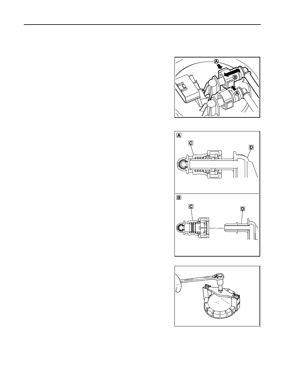
• Remove quick connector in the following procedures.
- NOTE:
• The figure show the process of quick connector disconnection. Parts arround quick connector could
have a different shape compare to the figure.
- Hold the sides of quick connector, press tabs and pull out fuel
feed tube.
- If quick connector sticks to tube of main fuel level sensor unit,
push and pull quick connectors several times until they start to
move. Then disconnect them by pulling.
CAUTION:
• Quick connector can be disconnected when the tabs are
depressed completely. Never twist it more than neces-
sary.
• Never use any tools to disconnected quick connector.
• Keep resin tube away from heat. Be especially careful
when welding near the resin tube.
• Prevent acid liquid such as battery electrolyte, etc. from
getting on resin tube.
• Never bend or twist resin tube during installation and dis-
connection.
• Never insert plug, preventing damage to O–ring in quick
connector.
• To keep the connecting portion clean and to avoid dam-
age and foreign materials, cover them completely with
plastic bags or something similar.
8.
Using lock ring wrench [SST: KV99104700], remove lock ring.
NOTE:
For reference when installing, put a matching mark on lock ring,
fuel level sensor unit and fuel tank.
A
: Push in tabs
B
: Pull
E1BIA1191ZZ
A
: Connection (cross-section)
B
: Disconnection (cross-section)
C
: Quick connector
D
: Hard tube
E1BIA1190ZZ
PBIC0240E
Нет комментариевНе стесняйтесь поделиться с нами вашим ценным мнением.
Текст