Nissan Qashqai J11. Manual — part 174
CO-100
< REMOVAL AND INSTALLATION >
[R9M]
WATER PUMP
WATER PUMP
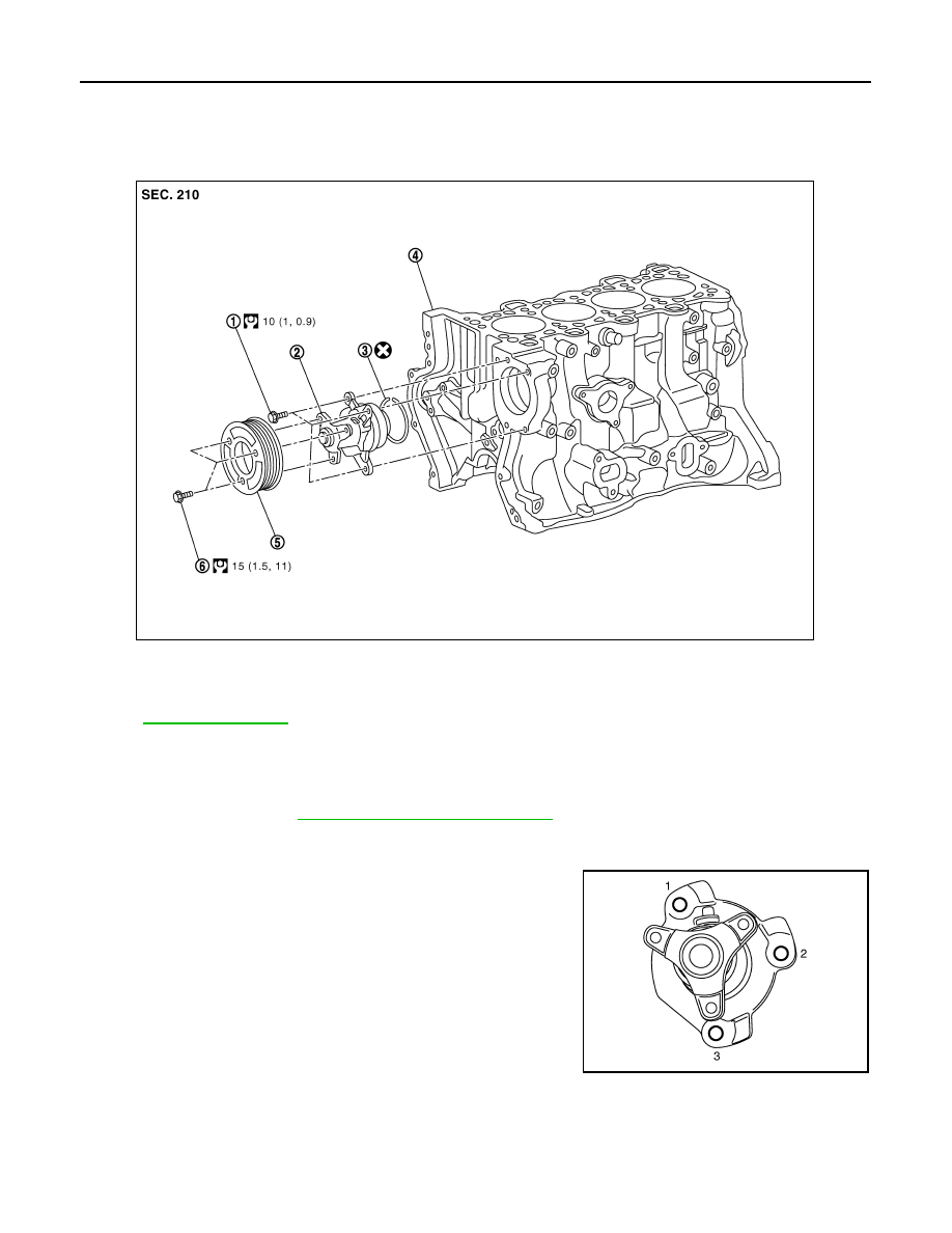
Exploded View
INFOID:0000000010416542
for symbols in the figure.
Removal and Installation
INFOID:0000000010416543
REMOVAL
1.
Remove engine. Refer to
EM-431, "Removal and Installation"
.
2.
Remove water pump pulley.
3.
Remove water pump.
• Loosen mounting bolts in reverse order as shown in the figure.
CAUTION:
• Handle water pump vane so that it does not contact any
other parts.
• Water pump cannot be disassembled and should be
replaced as a unit.
INSTALLATION
Note the following, and install in the reverse order of removal.
Water pump
1.
Water pump bolt
2.
Water pump
3.
O-ring
4.
Cylinder block
E1BIA0585GB
JPBIA0746ZZ

WATER PUMP
CO-101
< REMOVAL AND INSTALLATION >
[R9M]
C
D
E
F
G
H
I
J
K
L
M
A
CO
N
P
O
• Tighten mounting bolts in numerical order as shown in the figure.
• When inserting water pump end into cylinder block, apply a neutral
detergent to O-ring. Then insert it immediately.
Inspection
INFOID:0000000010416544
INSPECTION AFTER DISASSEMBLY
• Visually check if there is no significant dirt or rusting on water
pump body and vane (A).
• Check that there is no looseness in vane shaft, and that it turns
smoothly when rotated by hand.
• Replace water pump, if necessary.
JPBIA0746ZZ
JPBIA0747ZZ
CO-102
< REMOVAL AND INSTALLATION >
[R9M]
THERMO PLUNGER UNIT
THERMO PLUNGER UNIT
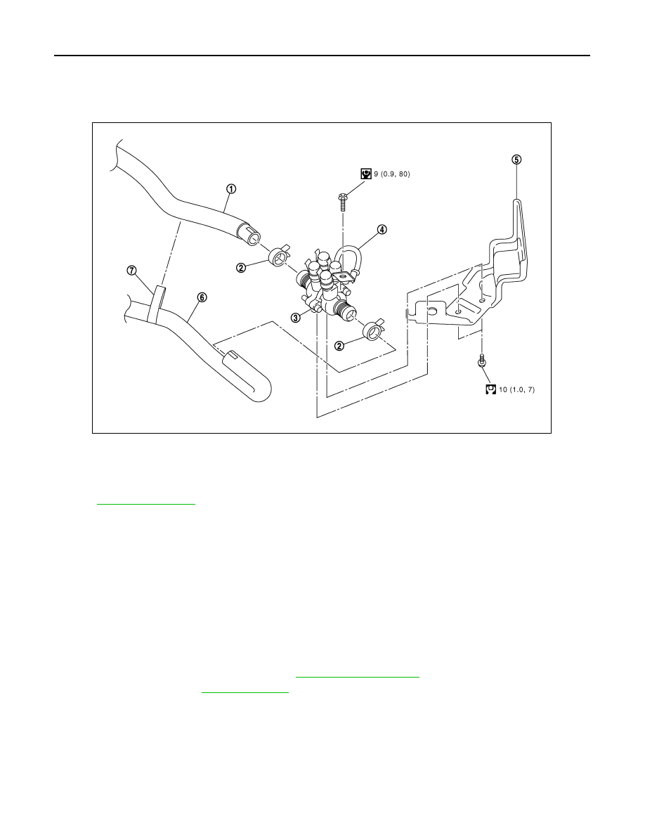
Exploded View
INFOID:0000000010438953
for symbol marks in the figure.
Removal and Installation
INFOID:0000000010438954
REMOVAL
CAUTION:
Make sure that the engine is cool down before operating, in order to avoid hot coolant outflow, as the
electric pump is turned on even if the engine is off. On the other hand the pump is turned off when the
engine is on. In this case as the electric pump is working, the thermostat will have to stay open due to
high temperatures.
1.
Remove the battery negative cable.
2.
Lift the vehicle.
3.
Remove front fender protector (LH). Refer to
4.
Drain the engine coolant.
5.
Remove the ground cable bolt.
6.
Disconnect thermo plunger unit connector.
7.
Remove the thermo plunger connection caps.
8.
Remove the thermo plunger connection nuts using the appropriate tool.
9.
Remove the water hose from thermo plunger unit.
10. Remove the thermo plunger unit fixing bolts.
11. Remove the thermo plunger unit.
1.
Water hose
2.
Clamp
3.
Thermo plunger control unit
4.
Earth lead
5.
Bracket stay
6.
Water hose
7.
Water hose clip
E1BIA1144GB

THERMO PLUNGER UNIT
CO-103
< REMOVAL AND INSTALLATION >
[R9M]
C
D
E
F
G
H
I
J
K
L
M
A
CO
N
P
O
INSTALLATION
NOTE:
• Thermo plunger caps must be correctly installed after removal.
• The hoses must be fully pushed onto pipe before tightening the clamp.
• Clamp must be fixed 5mm MIN from end of hose.
Installation is basically the reverse order of the removal.
Thermo plunger bracket stay bolt: 10 N.m (1 kg-m, 7 ft-lb)
Нет комментариевНе стесняйтесь поделиться с нами вашим ценным мнением.
Текст