Nissan Qashqai J11. Manual — part 594
STR-18
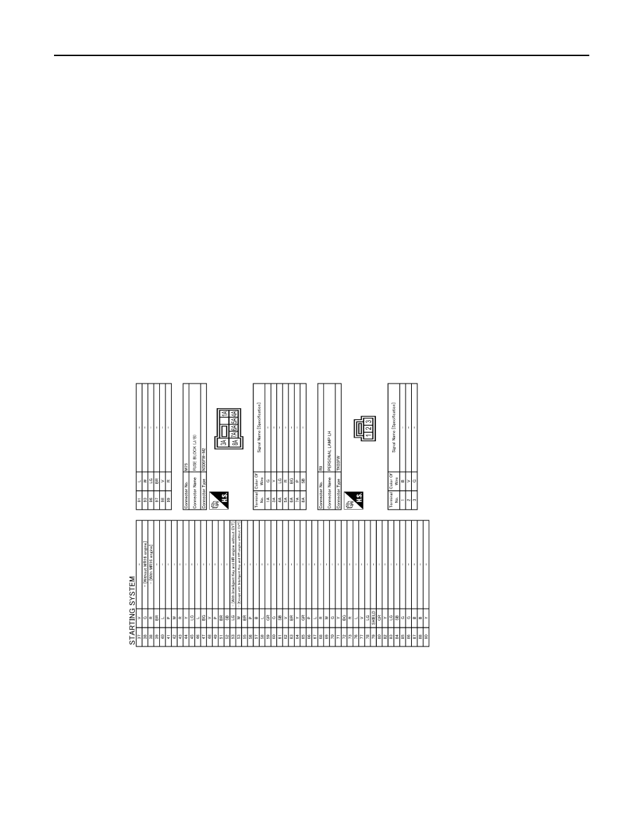
< WIRING DIAGRAM >
STARTING SYSTEM
JRBWD1456GB

DIAGNOSIS AND REPAIR WORK FLOW
STR-19
< BASIC INSPECTION >
C
D
E
F
G
H
I
J
K
L
M
A
STR
N
P
O
BASIC INSPECTION
DIAGNOSIS AND REPAIR WORK FLOW
Work Flow
INFOID:0000000010430894
DETAILED FLOW
NOTE:
If any malfunction is found, immediately disconnect the battery cable from the negative terminal.
CAUTION:
For models with stop/start system, erase the starter operation counter when the starter motor connec-
tor is disconnected. Refer to
(HR engine),
(K9K engine),
(R9M engine) or
engine).
1.
CHECK ENGINE TYPE
Check the vehicle information.
>> GO TO 2.
2.
CHECK ENGINE START
Crank the engine and check that the engine starts.
Does the engine start?
YES
>> GO TO 3.
NO
>> GO TO 4.
3.
CHECK THAT THE STARTER MOTOR STOPS
Check that the starter motor stops after starting the engine.
Does the starter motor stop?
YES
>> INSPECTION END
NO-1
>> Type 1: Replace starter motor.
NO-2
>> Type 2: Replace magnetic switch.
4.
CHECK THE ENGINE SPEED WITH CRANKING
Check that the engine runs at cranking.
Does engine turn by cranking?
YES
>> GO TO 5.
NO
>> GO TO 6.
5.
CHECK THE ENGINE SPEED WITH CRANKING
Check that the engine speed is not low at cranking.
Does engine turn normally?
YES
>> Check ignition/fuel system.
NO
>> Check charge condition, corrosion and connection condition of the battery. Refer to
"Work Flow WITHOUT STOP/START SYSTEM"
6.
CHECK STARTER MOTOR ACTIVATION
Check that the starter motor runs at cranking.
Does starter motor turn?
Type
Engine
1
HR engine
K9K engine
R9M engine
MR16DDT engine
2
MR20DD engine

STR-20
< BASIC INSPECTION >
DIAGNOSIS AND REPAIR WORK FLOW
YES-1 >> Type 1: Replace starter motor.
YES-2 >> Type 2: GO TO 7.
NO
>> GO TO 8.
7.
CHECK STARTER MOTOR UNIT
1.
Remove starter motor.
2.
Check that the gear shaft of starter motor rotates.
Does gear shaft turn?
YES
>> Check pinion clutch. Refer to
NO
>> Check reduction gear, armature and gear shaft.
8.
CHECK POWER SUPPLY CIRCUIT
Check the following conditions.
• Fuse and fusible link
• Charge condition, corrosion and connection condition of the battery. Refer to
Are these inspection results normal?
YES
>> GO TO 9.
NO
>> Repair as needed.
9.
CHECK STARTING SYSTEM WIRING
Check the following.
• “B” terminal circuit. Refer to
.
• “S” terminal circuit. Refer to
.
Are these inspection results normal?
YES-1 >> Type 1: Replace starter motor.
YES-2 >> Type 2: GO TO 10.
NO
>> Repair as needed.
10.
CHECK MAGNETIC SWITCH OPERATION SOUND
Check that a magnetic switch operation sound can be heard when the ignition switch is set at the starting posi-
tion.
Does magnetic switch operation sound occur?
YES
>> GO TO 11.
NO
>> Replace magnetic switch.
11.
PINION AND RING GEAR ENGAGEMENT CHECK
Check condition of pinion and ring gear mesh.
Is the inspection result normal?
YES
>> GO TO 13.
NO
>> GO TO 12.
12.
CHECK STARTER MOTOR UNIT
Check the following.
• Adjust pinion movement. Refer to
• Check pinion moving mechanism.
• Check ring gear.
Are these inspection results normal?
YES
>> INSPECTION END
NO
>> Repair or replace, if necessary.
13.
CHECK STARTER MOTOR UNIT
Check that the starter motor runs when connecting the positive terminal (12 V) to starter motor terminal M and
the negative terminal (ground) to starter motor body.
Does the starter motor run?
YES
>> Replace magnetic switch.
NO
>> Repair starter motor.

B TERMINAL CIRCUIT
STR-21
< DTC/CIRCUIT DIAGNOSIS >
C
D
E
F
G
H
I
J
K
L
M
A
STR
N
P
O
DTC/CIRCUIT DIAGNOSIS
B TERMINAL CIRCUIT
Diagnosis Procedure
INFOID:0000000010430895
CAUTION:
• Perform diagnosis under the condition that engine cannot start by the following procedure.
- Remove fuel pump fuse.
- Crank or start the engine (where possible) until the fuel pressure is released.
• For models with stop/start system, erase the starter operation counter when the starter motor con-
nector is disconnected. Refer to
(K9K engine),
(MR16DDT engine).
1.
CHECK “B” TERMINAL CIRCUIT 1
1.
Turn ignition switch OFF.
2.
Check that starter motor “B” terminal connection is clean and tight.
3.
Check voltage between starter motor “B” terminal and ground.
Except for MR engine
For MR engine
Is the inspection result normal?
YES
>> GO TO 2.
NO-1
>> For models with stop/start system: GO TO 4.
NO-2
>> For models without stop/start system: Check harness between battery and starter motor for open
circuit.
2.
CHECK BATTERY CABLE CONNECTION STATUS (VOLTAGE DROP TEST)
1.
Shift selector lever to “P” or “N” position. (CVT models)
Keep depressing clutch pedal fully. (M/T models)
2.
Check voltage between battery positive terminal and starter motor “B” terminal.
Except for MR engine
For MR engine
Is the inspection result normal?
YES
>> GO TO 3.
NO
>> Check harness between the battery and the starter motor for poor continuity.
(+)
(–)
Voltage (Approx.)
Starter motor
Connector
Terminal
F105
2 Ground
Battery
voltage
(+)
(–)
Voltage (Approx.)
Starter motor
Connector
Terminal
E70
2 Ground
Battery
voltage
(+)
(–)
Condition
Voltage (Approx.)
Starter motor
Connector
Terminal
Battery positive terminal
F105
2
When the ignition switch
is in START position
Less than
0.5 V
(+)
(–)
Condition
Voltage (Approx.)
Starter motor
Connector
Terminal
Battery positive terminal
E70
2
When the ignition switch
is in START position
Less than
0.5 V
Нет комментариевНе стесняйтесь поделиться с нами вашим ценным мнением.
Текст