Nissan Qashqai J11. Manual — part 92
TIMING BELT
EM-307
< REMOVAL AND INSTALLATION >
[K9K]
C
D
E
F
G
H
I
J
K
L
M
A
EM
N
P
O
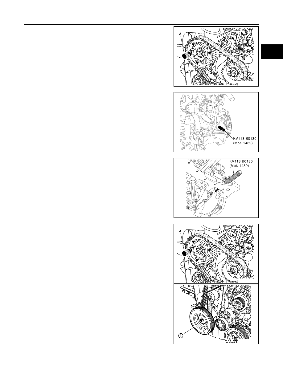
12. Insert TDC set pin [SST: KV113B0110 (Mot. 1430)] (A) into the
camshaft pulley and cylinder head hole.
13. Screw in the TDC pin (special service tool).
14. Turn the engine clockwise (timing side) until the crankshaft
reaches the TDC pin (special service tool).
15. The pin [SST: KV113B0110 (Mot. 1430)] (A) must engage in the
camshaft pulley and cylinder head holes.
16. Insert flat-bladed screwdriver into the place of crankshaft posi-
tion sensor to block crankshaft and loosen crankshaft pulley bolt
(1).
17. Remove crankshaft pulley.
CAUTION:
Never remove fixing bolts. Keep loosened fixing bolts in
place to protect removed crankshaft pulley from dropping.
MBIB1924E
MBIB0394E
MBIB0395E
MBIB1924E
MBIB1925E

EM-308
< REMOVAL AND INSTALLATION >
[K9K]
TIMING BELT
18. Slacken the timing belt by loosening the bolt of tensioner (1),
then remove timing belt.
INSTALLATION
Install in the reverse order of removal paying attention to the following.
TIMING ADJUSTMENT
CAUTION:
It is essential to degrease the end of the crankshaft, the bore of the crankshaft sprocket and the bear-
ing faces of the drive belt pulley to prevent any slip between the timing and the crankshaft which
would risk destroying the engine.
1.
Install timing belt tensioner.
NOTE:
Put the timing belt tensioner spigot (1) in the cylinder head
groove.
2.
Insert Tool KV113B0110 (Mot. 1430) (A) in the camshaft pulley
and cylinder head holes.
3.
Check that the mark on the high pressure pump pulley (2) has
shifted one tooth to the right of vertical axle.
4.
Turn crankshaft to set Tool KV113B0130 (Mot. 1489) (the crank-
shaft groove (1) must be facing upwards).
5.
Tighten old crankshaft pulley bolt with a spacer (1) (which does
not cover the timing sprocket mark).
MBIB1926E
MBIB1927E
MBIB1928E
MBIB1929E
TIMING BELT
EM-309
< REMOVAL AND INSTALLATION >
[K9K]
C
D
E
F
G
H
I
J
K
L
M
A
EM
N
P
O
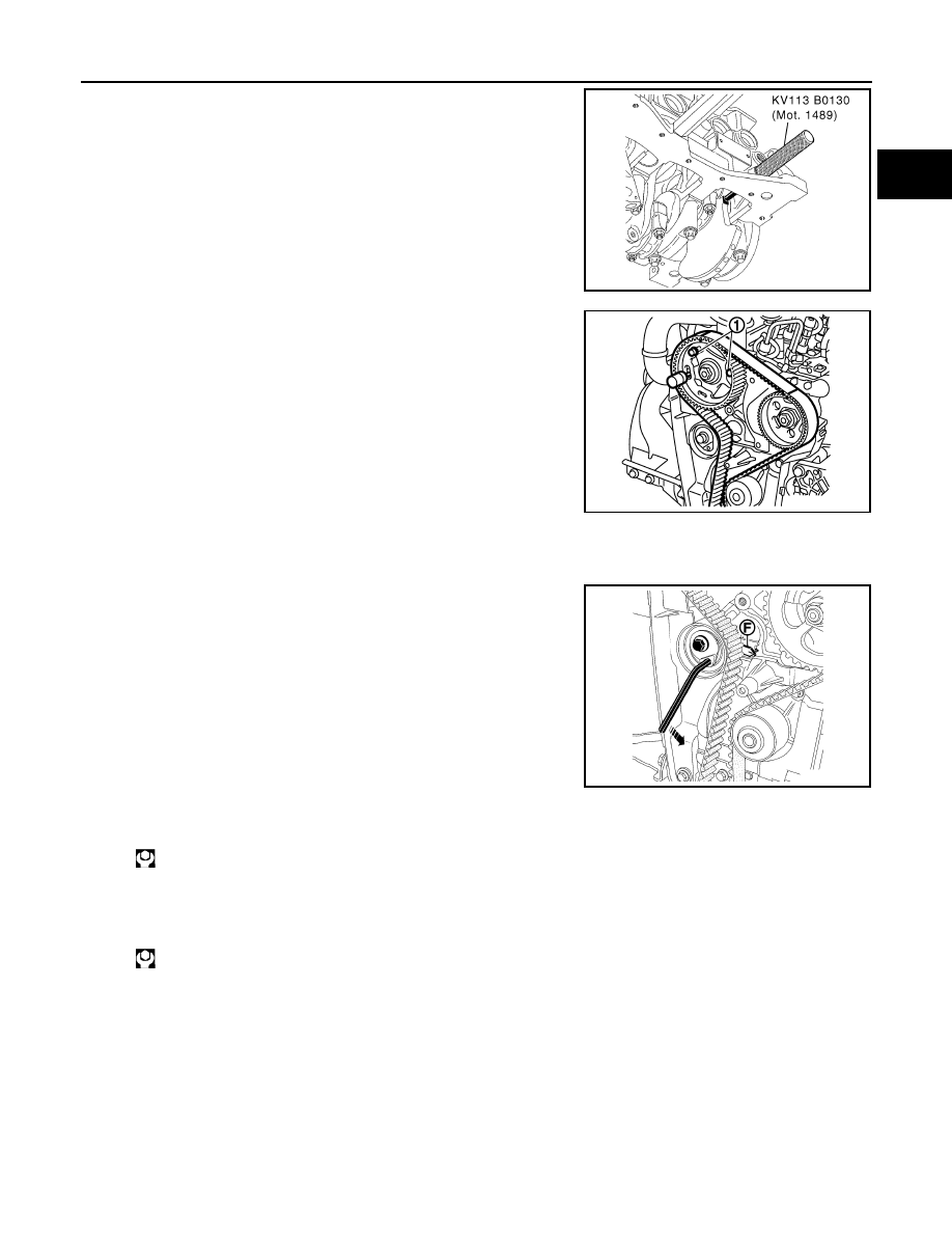
6.
Insert tool KV113B0130 (Mot. 1489) to crankshaft.
7.
Remove one wheel bolt from crankshaft pulley, and then loosen
the other two bolts (1).
8.
Install the timing belt, aligning the marks on the belt with those on the camshaft and fuel injection pump
sprockets (19 teeth spaces on the belt between the marks on the camshaft and pump sprockets).
9.
Using a 6 mm (0.24 in) Allen key, move the movable index (F) of
the tension wheel into the position shown below, by turning the
key counterclockwise.
10. Tighten the tension wheel bolt.
11. Check that the camshaft pulley wheel bolts are not fully up against the camshaft pulley wheel.
12. Install and tighten camshaft pulley wheel bolt.
13. Remove Tool KV113B0130 (Mot. 1489) and Tool KV113B0110 (Mot. 1430).
MBIB0395E
MBIB1930E
MBIB0509E
: 27 N·m (2.8 kg-m, 20 ft-lb)
: 14 N·m (1.4 kg-m, 10 ft-lb)
EM-310
< REMOVAL AND INSTALLATION >
[K9K]
TIMING BELT
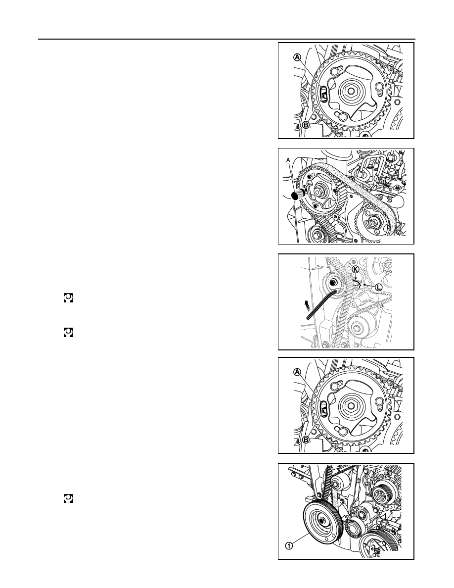
14. Turn the crankshaft two full turns in a clockwise direction (timing
side). Just before the hole (A) of the camshaft pulley is opposite
the cylinder head hole (B), insert tool KV113B0130 (Mot. 1489)
into the cylinder block.
15. Then turn the crankshaft slowly and smoothly against TDC set
pin.
16. Insert TDC set pin [SST: KV113B0110 (Mot. 1430)] (A).
If the pin cannot be inserted, perform the following.
a.
Remove TDC set pin [SST: KV113B0130 (Mot. 1489)].
b.
Loosen camshaft pulley wheel bolts.
c.
Turn camshaft pulley to adjust.
d.
Confirm that the crankshaft sprocket groove is facing upward.
e.
Loosen timing belt tensioner bolt.
f.
Move the movable index of the drive belt tensioner into the posi-
tion as shown in the figure, by turning the key clockwise.
g.
Tighten timing belt tensioner bolt.
h.
Install and tighten camshaft sprocket wheel bolts.
i.
Turn the crankshaft two revolutions in a clockwise direction (tim-
ing side). Just before the hole (A) of the camshaft pulley is oppo-
site the cylinder head hole (B), insert TDC set pin [SST:
KV113B0130 (Mot. 1489)] into the cylinder block.
j.
Then turn the crankshaft slowly and smoothly against TDC set
pin.
17. Install crankshaft pulley (1), and tighten the bolts as follows:
a.
Tighten the bolt.
b.
Turn the bolt 95 degrees
±
15 degrees clockwise (angle tighten-
ing).
MBIB1923E
MBIB1924E
: 27 N·m (2.8 kg-m, 20 ft-lb)
: 14 N·m (1.4 kg-m, 10 ft-lb)
MBIB0511E
MBIB1923E
: 120 N·m (12 kg-m, 89 ft-lb)
MBIB1925E
Нет комментариевНе стесняйтесь поделиться с нами вашим ценным мнением.
Текст