Nissan Qashqai J11. Manual — part 305
P0130 A/F SENSOR 1
ECM-197
< DTC/CIRCUIT DIAGNOSIS >
[MR20DD]
C
D
E
F
G
H
I
J
K
L
M
A
ECM
N
P
O
P0130 A/F SENSOR 1
DTC Description
INFOID:0000000010702921
DTC DETECTION LOGIC
To judge malfunctions, the diagnosis checks that the A/F signal computed by ECM from the A/F sensor 1 sig-
nal fluctuates according to fuel feedback control.
POSSIBLE CAUSE
• Harness or connectors (The A/F sensor 1 circuit is open or shorted.)
• A/F sensor 1
FAIL-SAFE
Not applicable
PERFORM DTC CONFIRMATION PROCEDURE
1.
PRECONDITIONING
If DTC Confirmation Procedure has been previously conducted, always turn ignition switch OFF and wait at
least 10 seconds before conducting the next test.
TESTING CONDITION:
Before performing the following procedure, confirm that battery voltage is 11 V or more at idle.
Will CONSULT be used?
YES
>> GO TO 2.
NO
>> GO TO 6.
2.
CHECK AIR FUEL RATIO (A/F) SENSOR 1 FUNCTION
WITH CONSULT
1.
Start engine and warm it up to normal operating temperature.
2.
Select “A/F SEN1 (B1)” in “DATA MONITOR” mode of “ENGINE” with CONSULT.
3.
Check “A/F SEN1 (B1)” indication.
Does the indication constantly fluctuate around 2.2 V?
YES
>> GO TO 3.
NO
>> Proceed to
ECM-198, "Diagnosis Procedure"
.
3.
PERFORM DTC CONFIRMATION PROCEDURE-1
1.
Select “ENGINE” of “A/F SEN1” in “DTC WORK SUPPORT” mode of “A/F (B1) P0130” with CONSULT.
2.
“TESTING” is displayed on the CONSULT screen when the following conditions are met.
CAUTION:
Always drive vehicle at a safe speed.
Is “TESTING” displayed on CONSULT screen?
YES
>> GO TO 4.
NO
>> If “TESTING” is not displayed after 20 seconds, GO TO 2.
4.
PERFORM DTC CONFIRMATION PROCEDURE-2
1.
Release accelerator pedal fully.
NOTE:
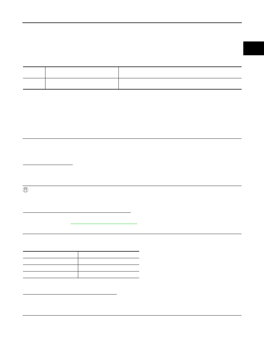
DTC No.
CONSULT screen terms
(Trouble diagnosis content)
DTC detecting condition
P0130
A/F SENSOR1 (B1)
(O2 sensor circuit bank 1 sensor 1)
The output voltage computed by ECM according to the A/F sensor 1 signal
is constant.
ENG SPEED
850 - 2,300 rpm
VHCL SPEED SE
More than 64 km/h (40 mph)
B/FUEL SCHDL
1.0 - 8.0 msec
Selector lever
Suitable position
ECM-198
< DTC/CIRCUIT DIAGNOSIS >
[MR20DD]
P0130 A/F SENSOR 1
Never operate brake pedal when releasing the accelerator pedal.
2.
Confirm that “TESTING” change to “COMPLETED”.
Is “COMPLETED” displayed on CONSULT screen?
YES
>> GO TO 5.
OUT OF CONDITION>>GO TO 3.
5.
PERFORM DTC CONFIRMATION PROCEDURE-3
Touch “SELF - DIAG RESULT”.
Is “OK” displayed on CONSULT screen?
YES-1 >> To check malfunction symptom before repair: Refer to
GI-41, "Intermittent Incident"
.
YES-2 >> Confirmation after repair: INSPECTION END
NO
ECM-198, "Diagnosis Procedure"
.
6.
PERFORM COMPONENT FUNCTION CHECK
WITHOUT CONSULT
NOTE:
Use component function check to check the overall function of the A/F sensor 1 circuit. During this check, a
1st trip DTC might not be confirmed.
1.
Start engine and warm it up to normal operating temperature.
2.
Shift the lever to suitable position and drive for a few minutes at 80 km/h (50 MPH).
CAUTION:
Always drive vehicle at a safe speed.
3.
Release the accelerator pedal fully until the vehicle speed decreases to 50 km/h (31 MPH).
NOTE:
Never apply brake when releasing the accelerator pedal.
4.
Repeat steps 2 and 3, 5 times.
5.
Stop the vehicle, turn ignition switch OFF and wait at least 10 seconds.
6.
Restart engine.
7.
Repeat steps 2 and 3, 5 times.
8.
Stop the vehicle and Check 1st trip DTC.
Is 1st trip DTC detected?
YES
>> Proceed to
ECM-198, "Diagnosis Procedure"
.
NO-1
>> To check malfunction symptom before repair: Refer to
GI-41, "Intermittent Incident"
.
NO-2
>> Confirmation after repair: INSPECTION END
Diagnosis Procedure
INFOID:0000000010702922
1.
CHECK AIR FUEL RATIO SENSOR 1 POWER SUPPLY
1.
Turn ignition switch OFF.
2.
Disconnect air fuel ratio (A/F) sensor 1 harness connector.
3.
Turn ignition switch ON.
4.
Check the voltage between A/F sensor 1 harness connector and ground.
Is the inspection result normal?
YES
>> GO TO 3.
NO
>> GO TO 2.
2.
CHECK AIR FUEL RATIO SENSOR 1 POWER SUPPLY CIRCUIT
1.
Turn ignition switch OFF.
2.
Disconnect IPDM E/R harness connector.
3.
Check the continuity between A/F sensor 1 harness connector and IPDM E/R harness connector.
+
Ground
Voltage
A/F sensor 1
Connector
Terminal
F74
4
Ground
Battery voltage

P0130 A/F SENSOR 1
ECM-199
< DTC/CIRCUIT DIAGNOSIS >
[MR20DD]
C
D
E
F
G
H
I
J
K
L
M
A
ECM
N
P
O
4.
Also check harness for short to ground and short to power.
Is the inspection result normal?
YES
>> Perform trouble diagnosis for power supply circuit.
NO
>> Repair or replace malfunctioning part.
3.
CHECK A/F SENSOR 1 INPUT SIGNAL CIRCUIT FOR OPEN AND SHORT
1.
Turn ignition switch OFF.
2.
Disconnect ECM harness connector.
3.
Check the continuity between A/F sensor 1 harness connector and ECM harness connector.
4.
Check the continuity between A/F sensor 1 harness connector and ground, or ECM harness connector
and ground.
5.
Also check harness for short to ground and short to power.
Is the inspection result normal?
YES
>> GO TO 4.
NO
>> Repair or replace malfunctioning part.
4.
REPLACE A/F SENSOR 1
Replace malfunctioning A/F sensor 1. Refer to
.
CAUTION:
• Discard any A/F sensor which has been dropped from a height of more than 0.5 m (19.7 in) onto a
hard surface such as a concrete floor; use a new one.
• Before installing new A/F sensor, clean exhaust system threads.
>> INSPECTION END
+
−
Continuity
A/F sensor 1
IPDM E/R
Connector
Terminal
Connector
Terminal
F74
4
F90
105
Existed
+
−
Continuity
A/F sensor 1
ECM
Connector
Terminal
Connector
Terminal
F74
1
F16
64
Existed
2
72
+
Ground
Continuity
A/F sensor 1
Connector
Terminal
F74
1
Ground
Not existed
2
+
Ground
Continuity
ECM
Connector
Terminal
F16
64
Ground
Not existed
72

ECM-200
< DTC/CIRCUIT DIAGNOSIS >
[MR20DD]
P0131 A/F SENSOR 1
P0131 A/F SENSOR 1
DTC Description
INFOID:0000000010702923
DTC DETECTION LOGIC
To judge the malfunction, the diagnosis checks that the A/F signal computed by ECM from the A/F sensor 1
signal is not inordinately low.
POSSIBLE CAUSE
• Harness or connectors (The A/F sensor 1 circuit is open or shorted.)
• The A/F sensor 1
FAIL-SAFE
Not applicable
DTC CONFIRMATION PROCEDURE
1.
PRECONDITIONING
If DTC Confirmation Procedure has been previously conducted, always turn ignition switch OFF and wait at
least 10 seconds before conducting the next test.
TESTING CONDITION:
Before performing the following procedure, confirm that battery voltage is 10.5 V or more at idle.
Will CONSULT be used?
YES
>> GO TO 2.
NO
>> GO TO 4.
2.
CHECK A/F SENSOR FUNCTION
WITH CONSULT
1.
Start engine and warm it up to normal operating temperature.
2.
Select “A/F SEN1 (B1)” in “DATA MONITOR” mode of “ENGINE” system with CONSULT.
3.
Check “A/F SEN1 (B1)” indication.
Is the indication constantly approx. 0 V?
YES
>> Proceed to
ECM-201, "Diagnosis Procedure"
.
NO
>> GO TO 3.
3.
PERFORM DTC CONFIRMATION PROCEDURE
1.
Turn ignition switch OFF and wait at least 10 seconds.
2.
Drive and accelerate vehicle to more than 40 km/h (25 MPH) within 20 seconds after restarting engine.
CAUTION:
Always drive vehicle at a safe speed.
3.
Maintain the following conditions for approximately 20 consecutive seconds.
NOTE:
• Keep the accelerator pedal as steady as possible during cruising.
• If this procedure is not completed within 1 minute after restarting engine at step 1, return to step 1.
4.
Check 1st trip DTC.
Is 1st trip DTC detected?
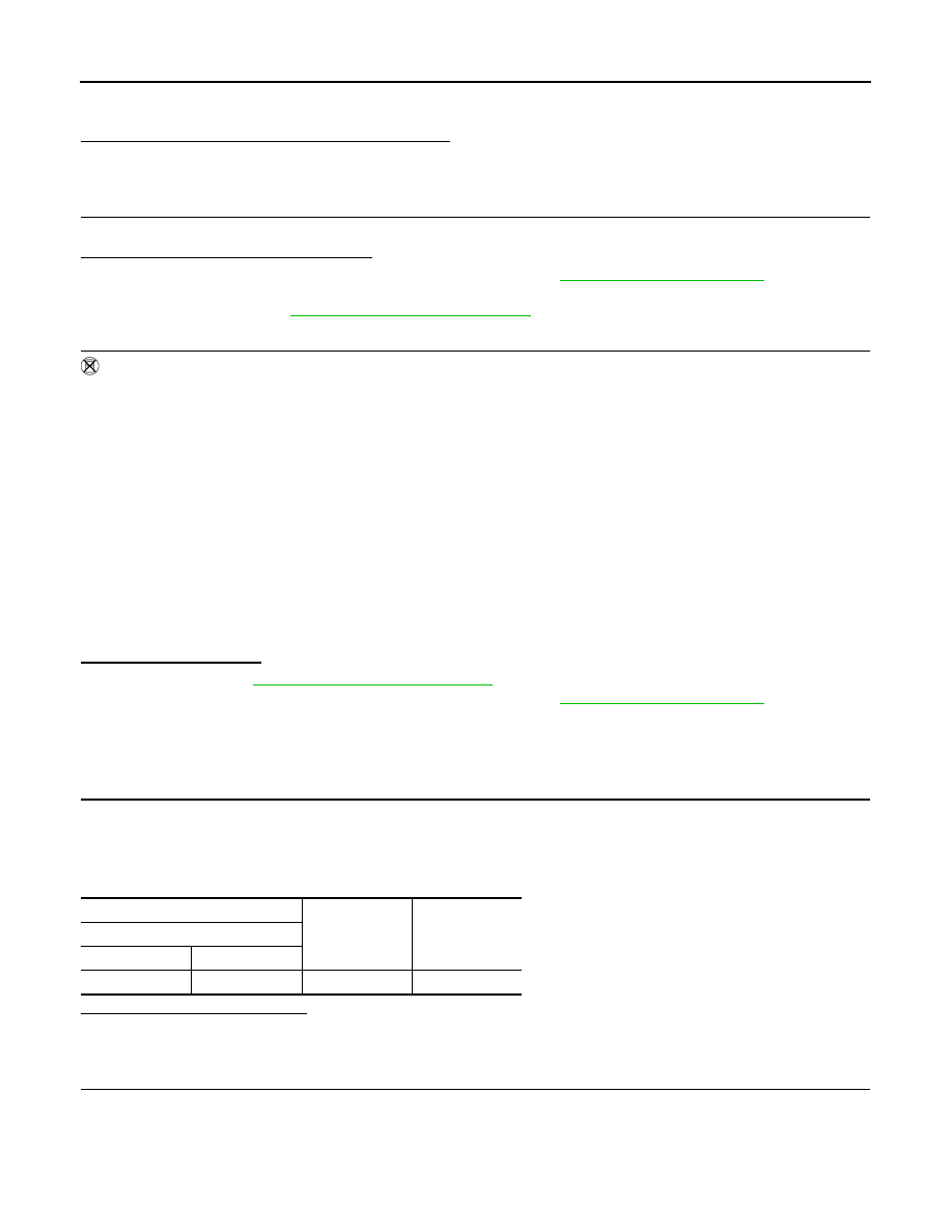
DTC No.
CONSULT screen terms
(Trouble diagnosis content)
DTC detecting condition
P0131
A/F SENSOR1 (B1)
(O2 sensor circuit low voltage bank 1 sen-
sor 1)
The output voltage computed by ECM according to the A/F sensor 1 signal
is excessively low at all times.
ENG SPEED
1,000 - 3,200 rpm
VHCL SPEED SE
More than 40 km/h (25 mph)
VHCL SPEED SE
1.5 - 9.0 msec
Selector lever
Suitable position
Нет комментариевНе стесняйтесь поделиться с нами вашим ценным мнением.
Текст